
Steel sheet laminating device

A bonding device and steel sheet technology, applied in lamination devices, lamination auxiliary operations, lamination, etc., can solve problems such as easy to break the vacuum, difficult to control the tension of the material belt, and slow bonding efficiency, so as to ensure smoothness Sexuality, avoid blanking, and avoid damage to the product

Pending Publication Date: 2020-07-03
SUZHOU LANGKUN AUTOMATION EQUIP CO LTD
View PDF0 Cites 2 Cited by
  • Summary
  • Abstract
  • Description
  • Claims
  • Application Information

AI Technical Summary

Problems solved by technology

[0002] The steel sheet laminating machine is to attach the cut steel sheet to the 3C product. The steel sheet lamination is an important step in the processing of the 3C product. The existing steel sheet laminating machine is to peel off the steel sheet coil The steel sheets that come out are attached to the product, and the lamination efficiency is slow, and the lamination of the steel sheets cannot realize integrated production. At the same time, the separation of the loading and unloading mechanism increases the input of manpower and increases the production cost. Driven by a motor, when the steel sheet is attached to the product, the product belt needs to be suspended. At this time, the tension of the material belt is difficult to control. For small products, the width of the steel sheet is 0.01mm ~ 0.02mm, and the ordinary suction cup is large, which is difficult to absorb the steel. sheet, the vacuum is easy to break during the adsorption process, and the single adsorption efficiency is low. Based on the above defects and deficiencies, it is necessary to improve the existing technology and design a steel sheet bonding device

Method used


Image

  • Steel sheet laminating device
  • Steel sheet laminating device
  • Steel sheet laminating device

Examples


Embodiment Construction

[0027] The preferred embodiments of the present invention will be described in detail below in conjunction with the accompanying drawings, so that the advantages and features of the invention can be more easily understood by those skilled in the art, so as to define the protection scope of the present invention more clearly.

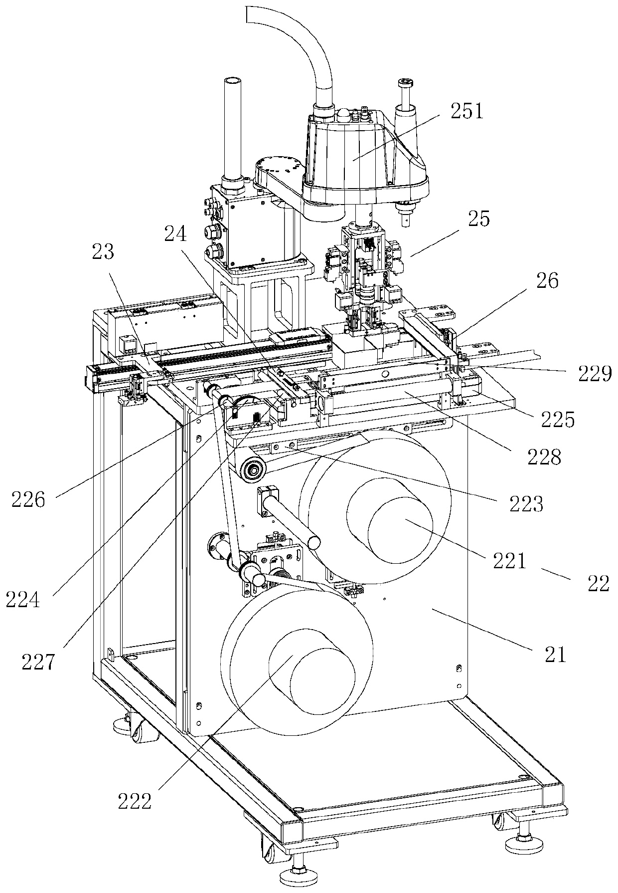
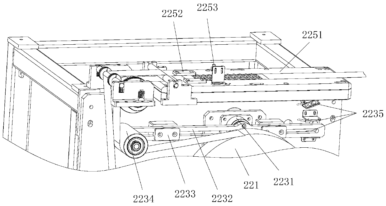
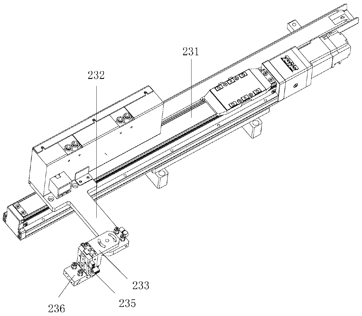
[0028] see Figure 1 to Figure 9 , the embodiment of the present invention includes:

[0029] A steel sheet bonding device, the steel sheet bonding device includes a bonding frame 21, a PC film feeding unit 22, an adjustable steel sheet transplanting manipulator 23, a steel sheet positioning adsorption platform 24, a bonding manipulator 25 and Press assembly 26, PC film feeding unit 22 is installed on the laminating frame 21, adjustable steel sheet transplanting manipulator 23, steel sheet positioning adsorption platform 24, laminating manipulator 25 are arranged on PC film feeding unit 22 And the pressing assembly 26, the adjustable steel sheet transpl...


PUM


Abstract

The invention discloses a steel sheet laminating device. The steel sheet laminating device comprises a laminating rack, a PC film feeding unit, an adjustable steel sheet transplanting manipulator, a steel sheet positioning adsorption platform, a laminating manipulator and a pressing assembly, wherein the PC film feeding unit is mounted on the laminating rack, the adjustable steel sheet transplanting manipulator, the steel sheet positioning adsorption platform, the laminating manipulator and the pressing assembly are arranged on the PC film feeding unit, the adjustable steel sheet transplantingmanipulator grabs a steel sheet at a steel sheet punching device and then places the steel sheet on the steel sheet positioning adsorption platform, the laminating manipulator adsorbs and laminates the steel sheet on the PC film, and the pressing assembly presses the steel sheet on the PC film. By means of the mode, the device is compact in structure, stable in operation and capable of automatically adjusting the feeding tightness, guaranteeing the feeding stability, adjusting the levelness of the adsorption holes in the bottom face of the adsorption block, positioning and adsorbing steel sheets, facilitating subsequent steel sheet adsorption and product pressing and pasting and meanwhile avoiding product damage.

Description

technical field [0001] The invention relates to the technical field of lamination of steel sheets, in particular to a lamination device of steel sheets. Background technique [0002] The steel sheet laminating machine is to attach the cut steel sheet to the 3C product. The steel sheet lamination is an important step in the processing of the 3C product. The existing steel sheet laminating machine is to peel off the steel sheet coil The steel sheets that come out are attached to the product, and the lamination efficiency is slow, and the lamination of the steel sheets cannot realize integrated production. At the same time, the separation of the loading and unloading mechanism increases the input of manpower and increases the production cost. Driven by a motor, when the steel sheet is attached to the product, the product belt needs to be suspended. At this time, the tension of the material belt is difficult to control. For small products, the width of the steel sheet is 0.01mm ...

Claims


Application Information

Patent Timeline
Patent Type & Authority Applications(China)
IPC IPC(8): B32B37/00B32B37/12B32B38/00B32B38/10
CPCB32B37/0053B32B37/12B32B38/0008B32B38/10
Inventor 王柱佟云辉谢桥清陈海林郑贵军
Owner SUZHOU LANGKUN AUTOMATION EQUIP CO LTD
Learn More