Particle screening device for mechanical production

A screening device and particle technology, which is applied in the direction of filter screen, solid separation, grid, etc., can solve the problems of unsatisfactory screening effect and so on.

Inactive Publication Date: 2020-10-20
宣城知明灯机械设计有限公司
View PDF1 Cites 2 Cited by
  • Summary
  • Abstract
  • Description
  • Claims
  • Application Information

AI Technical Summary

Problems solved by technology

[0004] Based on the technical problem of unsatisfactory screening effect of existing devi

Method used


Image

  • Particle screening device for mechanical production
  • Particle screening device for mechanical production
  • Particle screening device for mechanical production

Examples


Example Embodiment

[0024] Example 1

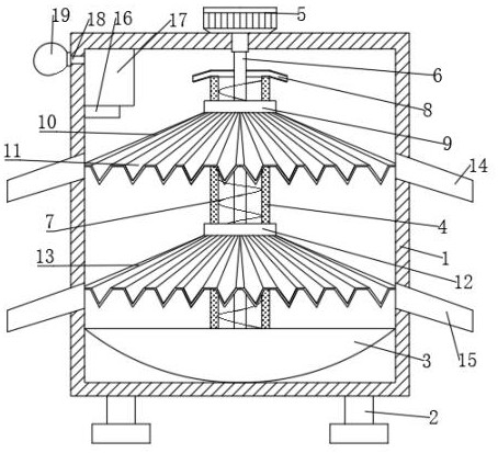
[0025] refer to Figure 1-4 , a particle screening device for mechanical production, including a box body 1, a plurality of pillars 2 are symmetrically fixed by bolts on both sides of the bottom of the box body 1, a motor 5 is fixed on the top of the box body 1 by bolts, and the output shaft of the motor 5 runs through the box body 1 is connected with a straight shaft 6, and the bottom of the inner wall of the box body 1 is fixed with a collection basin 3 by bolts. Inside the guide tube 4, the bottom of the straight shaft 6 is rotatably connected to the bottom of the inner wall of the guide tube 4, and the outer wall of the straight shaft 6 is welded with jiaolong blades 7, and the top of the guide tube 4 is fixed with a guide plate 8 by bolts, and the guide plate 8 and the guide tube 4 is connected, the straight shaft 6 and the material guide plate 8 are connected through, the outer wall of the guide pipe 4 is fixed with bolts to the first fixed ring 9 and...

Example Embodiment

[0028] Example 2

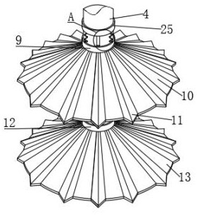
[0029] refer to Figure 1-5 , a particle screening device for mechanical production, the top of the first screen plate 10 is welded with a plurality of deceleration discs 29, the plurality of deceleration discs 29 are arranged in an annular array distribution, and the plurality of deceleration discs 29 are equally divided into a plurality of guide grooves 11, the cross-section of the deceleration plate 29 is arranged in a silkworm shape, and the deceleration plate 29 in the guide groove 11 is arranged in an arrangement from dense to sparse from inside to outside.

[0030] When in use, the deceleration plate 29 can block and decelerate the small particles at the bottom of the guide groove 11, prolong the movement time of the small particles on the first screen plate 11, and make the small particles move on the first screen plate 11. The path is completely screened to prevent small particles and large particles from being discharged from the first discharge p...


PUM


Abstract

The invention belongs to the technical field of machining, particularly relates to a particle screening device for mechanical production. The particle screening device aims to solve the problem that an existing device is not ideal in screening effect. According to the scheme, the particle screening device comprises a box body, wherein a motor is fixed to the top of the box body, and an output shaft of the motor is connected with a straight shaft; a collecting basin is fixed to the bottom of the inner wall of the box body, a guide pipe is fixed to the bottom of the inner wall of the collectingbasin, and a first fixing ring and a second fixing ring are fixed to the outer wall of the guide pipe; and a first screen plate and a second screen plate are fixed to the bottom of the first fixing ring and the bottom of the second fixing ring respectively, and the first screen plate and the second screen plate are arranged to be of hollow circular truncated cone structures. According to the particle screening device for mechanical production, the first screen plate is arranged to be of the hollow circular truncated cone structure, a plurality of guide grooves are formed in the first screen plate, and the sections of the guide grooves are arranged in V shapes, so that the contact area and capacity are effectively increased; and small particles are located at the bottoms of the guide grooves, large particles are located at the upper portions of the guide grooves, and the large and small particles are evenly screened in a layered mode, so that the screening effect of the device is improved.

Description

technical field [0001] The invention relates to the technical field of mechanical processing, in particular to a particle screening device for mechanical production. Background technique [0002] Machining refers to the process of changing the shape, size or performance of a workpiece through a mechanical device. According to the difference in processing methods, it can be divided into cutting processing and pressure processing. In the production process, any change in the shape, size, Position and nature, etc., the process of making it into a finished product or semi-finished product is called a process, which is the main part of the production process, and the process can be divided into casting, forging, stamping, welding, machining, assembly and other processes, mechanical manufacturing The process generally refers to the sum of the mechanical processing process of the parts and the assembly process of the machine, and other processes are called auxiliary processes. [...

Claims


Application Information

Patent Timeline
IPC IPC(8): B07B1/34B07B1/42B07B1/46
CPCB07B1/343B07B1/42B07B1/4663B07B2201/04
Inventor 郝明明赵姣凤
Owner 宣城知明灯机械设计有限公司
Why Eureka
Try Eureka