
Vane-type camshaft adjuster

a camshaft and camshaft technology, applied in the direction of manufacturing tools, machines/engines, couplings, etc., can solve the problems of still generated corner stresses, and achieve the effect of reducing stresses

Active Publication Date: 2007-03-13
SCHAEFFLER TECH AG & CO KG
View PDF2 Cites 1 Cited by
  • Summary
  • Abstract
  • Description
  • Claims
  • Application Information

AI Technical Summary

Benefits of technology

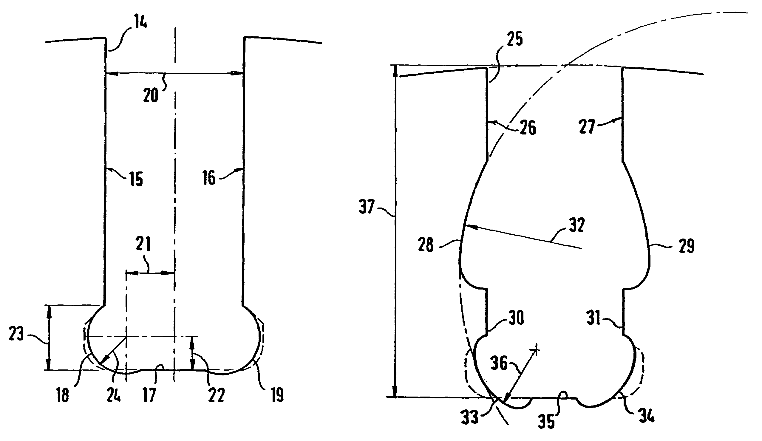
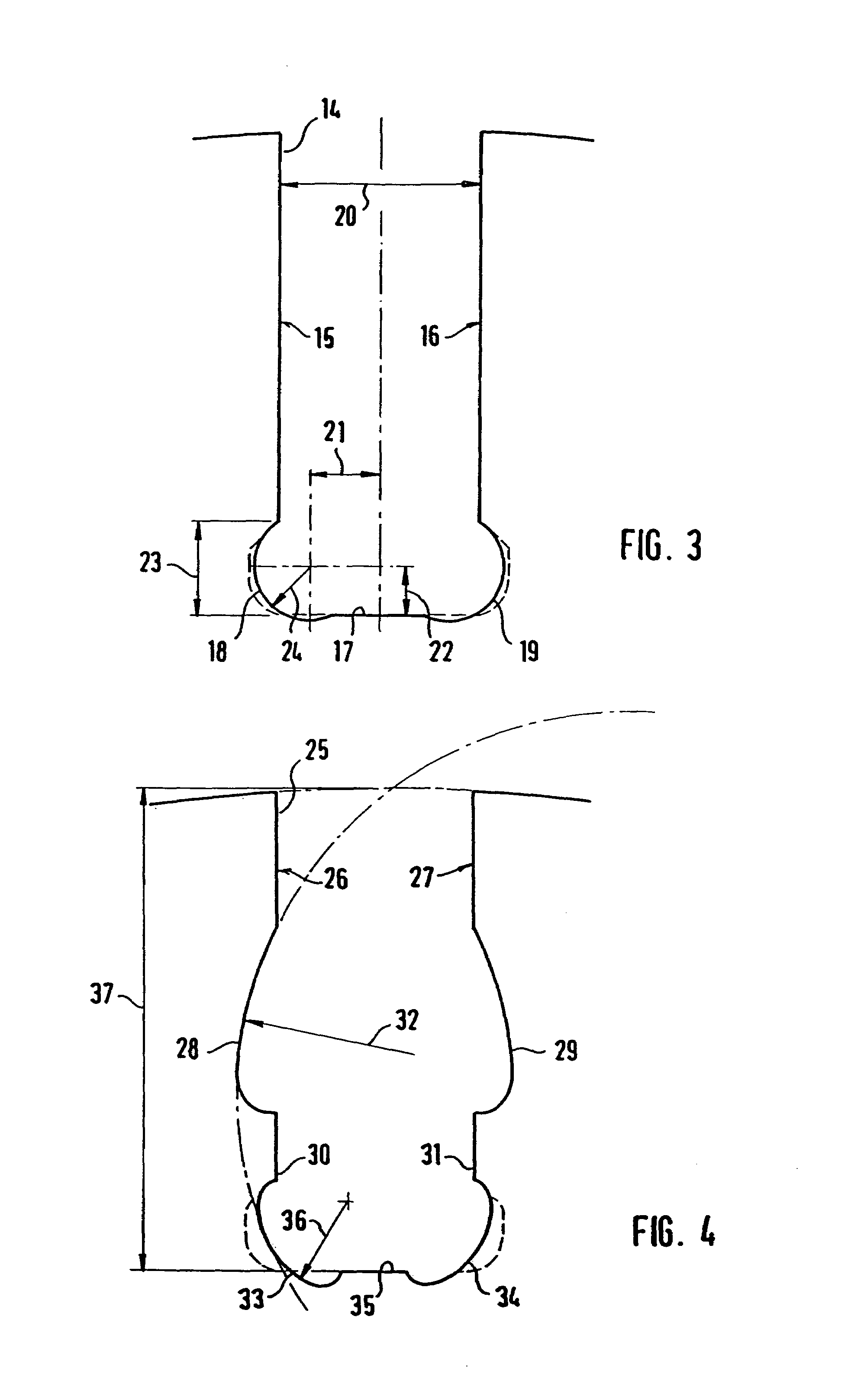
The invention is a vane-type camshaft adjuster that reduces stress on the components. This is achieved by shaping the rounded transition regions of the camshaft adjuster as circular arc segments that undercut the groove bottom. The ratio of the distance of the lower end of the groove side face from the groove bottom to the groove width should be 0.4 to 0.55, with a preferred value of 0.48. The radius of the circular arc segments should amount to 0.5 to 0.6 times the distance from the lower end of the groove side face to the groove bottom, with a preferred value of 0.55. The horizontal distance of the midpoint of the circular arc segment to the groove bottom should amount to 0.90 times the radius of the circular arc segment, with a preferred value of 0.95. A relief notch can also be used to further reduce stress concentration. The invention also suggests using a groove side face with an optimized shape and a radius of the circular arc segments in the region of the groove bottom of 0.20 to 0.28 times the radius of the circular arc segments in the region of the relief notch. These features and advantages can lead to cost savings and improved performance.

Problems solved by technology

However, considerable stresses still are generated in the corner region, which, under the usual operating loads, can be critical to the materials used.

Method used


Image

  • Vane-type camshaft adjuster
  • Vane-type camshaft adjuster
  • Vane-type camshaft adjuster

Examples


Embodiment Construction

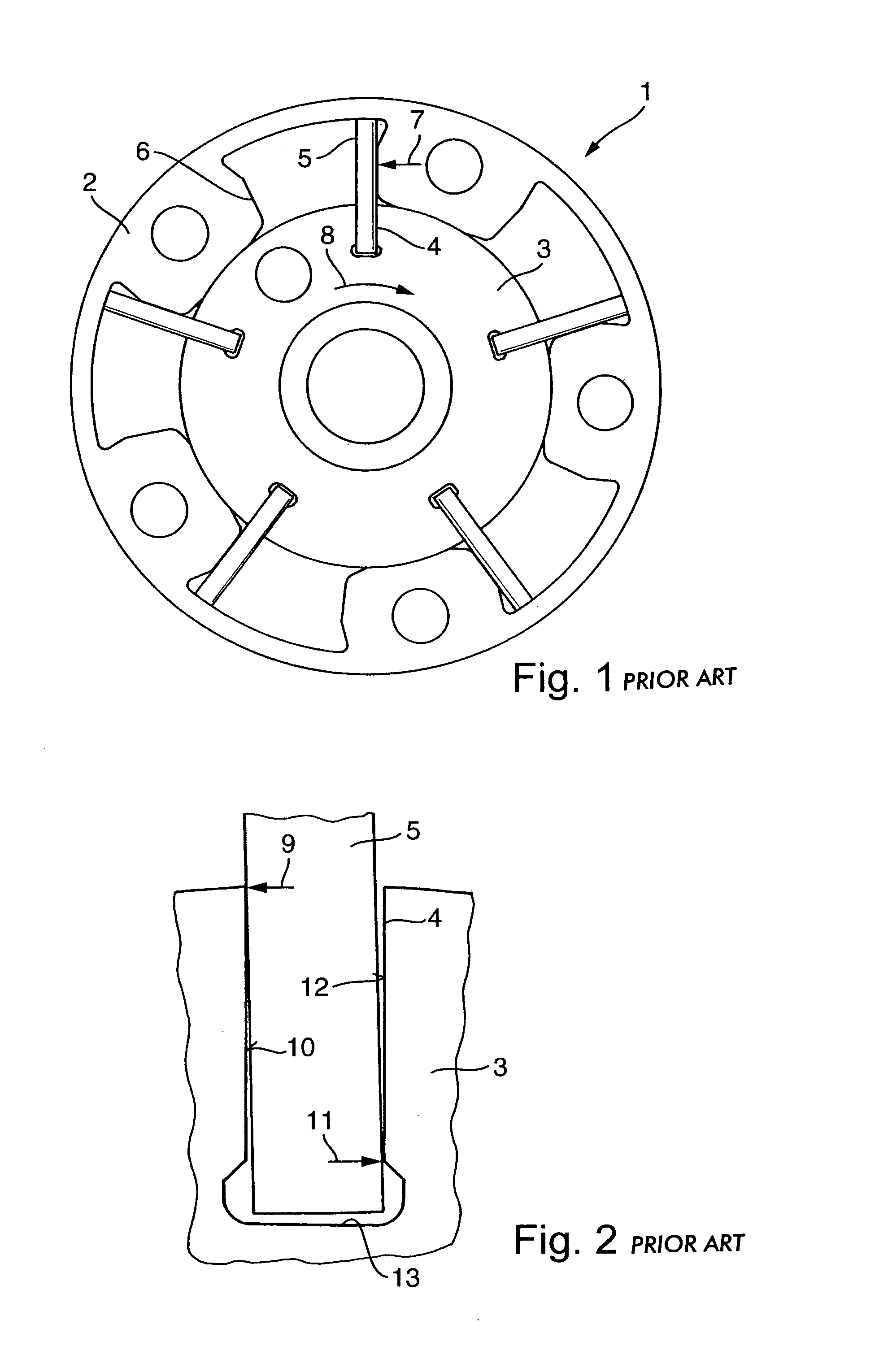
[0024]FIG. 1 shows a conventional vane-type camshaft adjuster 1 comprising a stator 2, and a rotor 3 having a plurality of blades 5 inserted in blade grooves 4 in the rotor.

[0025]The stator 2 is part of a chain or belt drive, whereby the rotation of the crankshaft is transmitted by a chain or a belt, via the stator 2 and the rotor 3, to a camshaft. The stator 2 has projections 6, which serve as stops for the blades 5. In FIG. 1, the blade 5 is in an end position. In the rotor 3, on the left and right side of each blade groove 4, there are bores, through which a fluid can flow in or out of a chamber alongside the blade 5. As a result of the inflowing or outflowing fluid, a relative rotation between the rotor 3 and the stator 2, and thus between the crankshaft and the camshaft of an internal combustion engine, is obtained.

[0026]The blade 5 is acted upon by the force 7 represented as an arrow, which is opposed by the torque 8 acting upon the shaft of the rotor 3.

[0027]FIG. 2 shows an e...


PUM

PropertyMeasurementUnit
widthaaaaaaaaaa
radiusaaaaaaaaaa
horizontal distanceaaaaaaaaaa

Abstract

A vane-type camshaft adjuster having a stator, and a rotor connectable to a camshaft. The rotor has a plurality of radially protruding blades inserted in respective blade grooves. The blade groove has groove side faces, a groove bottom and rounded transition regions between the groove side faces and the groove bottom. The transition regions undercut the groove side faces, wherein the rounded transition regions are configured, at least in part, as circular arc segments which undercut the groove bottom.

Description

FIELD OF THE INVENTION[0001]The invention relates to a vane-type camshaft adjuster having a stator and a rotor. The rotor can be connected to a camshaft. The rotor comprises a plurality of radially protruding blades inserted in blade grooves. The blades extend into the stator. A blade groove has groove side faces, a groove bottom and rounded transition regions between the groove side faces and the groove bottom, which transition regions undercut the groove side faces.BACKGROUND OF THE INVENTION[0002]Camshaft adjusters are used to alter the control times for the opening or closing of valves. The fixed angular relationship between the camshaft and the crankshaft which drives it is eliminated and the control times can be optimally set as a function of the rev speed and further parameters. Camshaft adjusters allow the camshaft to be twisted relative to the crankshaft.[0003]Known vane-type camshaft adjusters have a rotor comprised of a plurality of radially protruding blades, which are u...

Claims


Application Information

Patent Timeline
Patent Type & Authority Patents(United States)
IPC IPC(8): F01L1/34F01L1/344
CPCF01L1/3442F01L2820/01B23D47/00B23D47/08B23D47/04B23D61/02
Inventor KOHRS, MIKEGOLBACH, HERMANN
Owner SCHAEFFLER TECH AG & CO KG
Learn More