

Flow passage structure of regenerative pump
A regenerative, flow channel technology, applied in non-variable pumps, non-volume pumps, pumps, etc., can solve problems affecting pump performance and noise
- Summary
- Abstract
- Description
- Claims
- Application Information
AI Technical Summary
Problems solved by technology
Method used
Image

Examples
Embodiment Construction
[0040] In order to further understand and understand the features, purposes and functions of the present invention, a detailed description is given below with reference to the drawings:
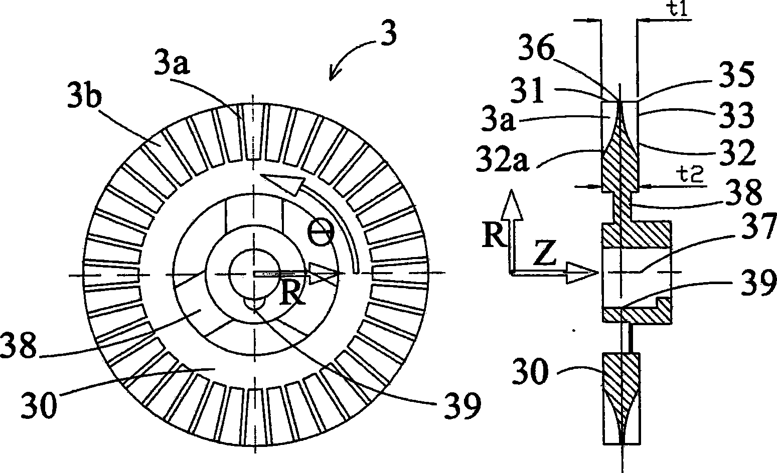
[0041] Please refer to Fig. 5, it is one of the embodiments of the present invention in the closed impeller, and the impeller 3 is a disc-shaped structure, and several radial blades are arranged on both sides of the outer edge of the disc, and the corresponding blades on the same side The space between two adjacent blades constitutes a radial channel, and the structure of the blades includes a blade inlet 32, a blade side plate 34, a blade outlet 31 and a blade hub plate 36, and the shaft hole 37 of the central hub of the impeller 3 is provided with The keyway 39 is used to smoothly connect the motor shaft, and several ribs 38 are connected between the hub and the disc at the root of the blade 30. The axial coordinate of the impeller structure is the z axis, the radial coordinate is the r axis...
PUM
 Abstract
Description
Claims
Application Information