Flowing electrolyte fuel cell with improved performance and stability

a fuel cell and flow electrolyte technology, applied in the direction of cell components, electrolyte stream management, electrochemical generators, etc., can solve the problems of limited ionic active species transport rate, adverse effects on the performance characteristics of intermediate temperature dhcfcs based on previous designs, and significant challenges in finding appropriate materials to work in these conditions. , to achieve the effect of maximizing voltage delivering capability and maximizing current delivering capability

Inactive Publication Date: 2019-10-15
XEROX CORP
View PDF7 Cites 1 Cited by
  • Summary
  • Abstract
  • Description
  • Claims
  • Application Information

AI Technical Summary

Benefits of technology

[0012]In another aspect of the presently described embodiments, the system further comprises a dual-porosity membrane configured to allow uniform flow of fuel on a fuel side of the at least one fuel cell and prevent mixing of the fuel with the liquid electrolyte.
[0029]In another aspect of the presently described embodiments, the system comprises a stack of fuel cells electrically connected in a parallel configuration to maximize current delivering capability.
[0030]In another aspect of the presently described embodiments, the system comprises a stack of fuel cells electrically connected in a series configuration to maximize voltage delivering capability.
[0032]In another aspect of the presently described embodiments, an electrochemical fuel cell system employing the use of a fuel for electrochemical energy conversion and at least one fuel cell, the at least one fuel cell comprises a fuel inlet, a fuel outlet, a liquid electrolyte, and, a dual-porosity membrane configured to allow uniform flow of fuel between the fuel inlet and fuel outlet to prevent mixing of the fuel with the liquid electrolyte.
[0041]In another aspect of the presently described embodiments, a method for use in an electrochemical fuel cell system employing the use of a fuel for electrochemical energy conversion and at least one fuel cell, the method comprises receiving a liquid electrolyte in a saturated state, facilitating a flow of the liquid electrolyte in a flow path and allowing for an exit of the flowing liquid electrolyte in a depleted state.

Problems solved by technology

), and finding appropriate materials that work in these conditions is a significant challenge.
However, the performance characteristics of intermediate temperature DHCFCs based on previous designs can be adversely impacted by the limited rate of transport of the ionic active species (i.e. superoxide / oxide / peroxide ion) in the electrolyte.
For example, the performance characteristics (current density and specific power) of the DHCFC can be negatively affected by reduced concentration of oxygen in the electrolyte, or by the low rate of diffusion / transport of the oxygen ion through the electrolyte.
While redox anodic reactions are typically fast, the energy efficiency of a metal-air battery is limited by the kinetics of the oxygen reduction reaction (ORR).

Method used


Image

  • Flowing electrolyte fuel cell with improved performance and stability
  • Flowing electrolyte fuel cell with improved performance and stability
  • Flowing electrolyte fuel cell with improved performance and stability

Examples


Embodiment Construction

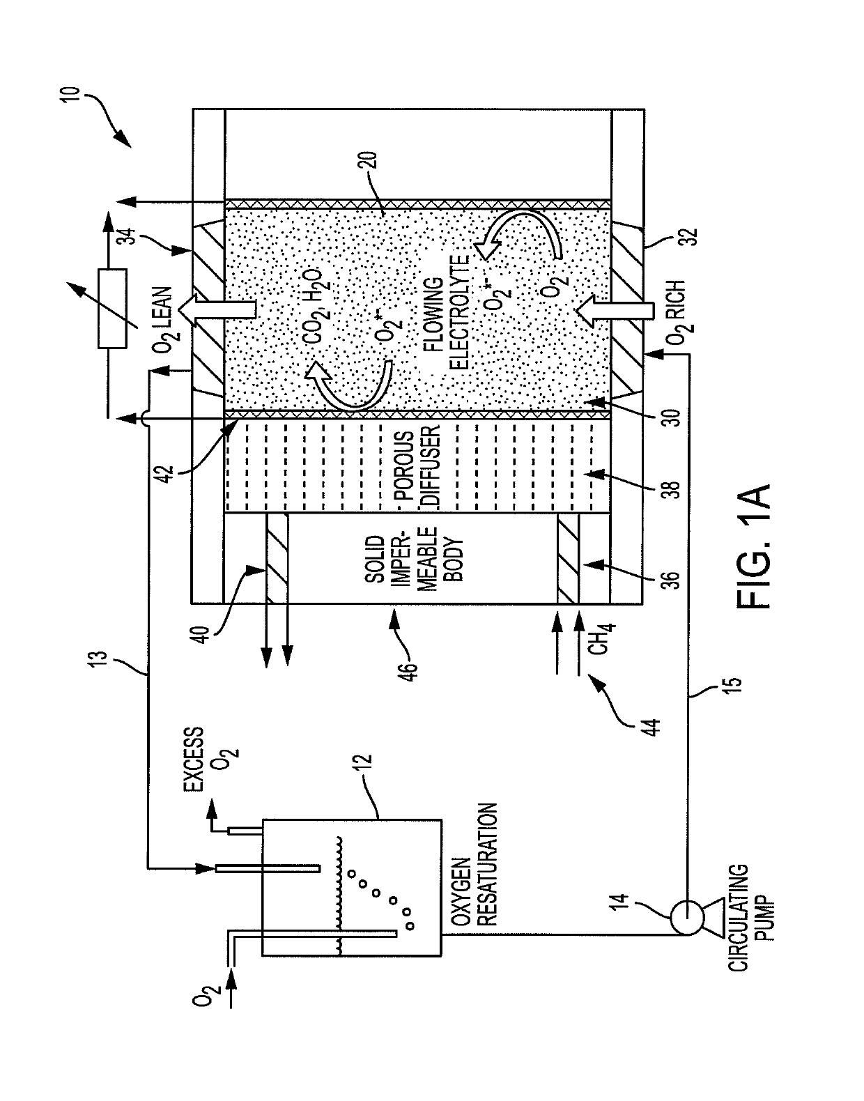
[0053]According to the presently described embodiments, the use of convection / electrolyte flow helps eliminate concentrations gradients and further enhances the diffusional current in contemplated systems. Also, according to the presently described embodiments, improving the use of an oxygen-saturated electrolyte results in improved performance (specific power and energy) and energy efficiency of such systems.

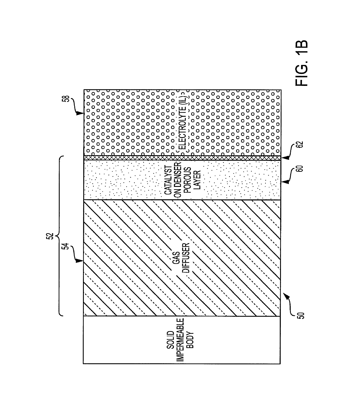
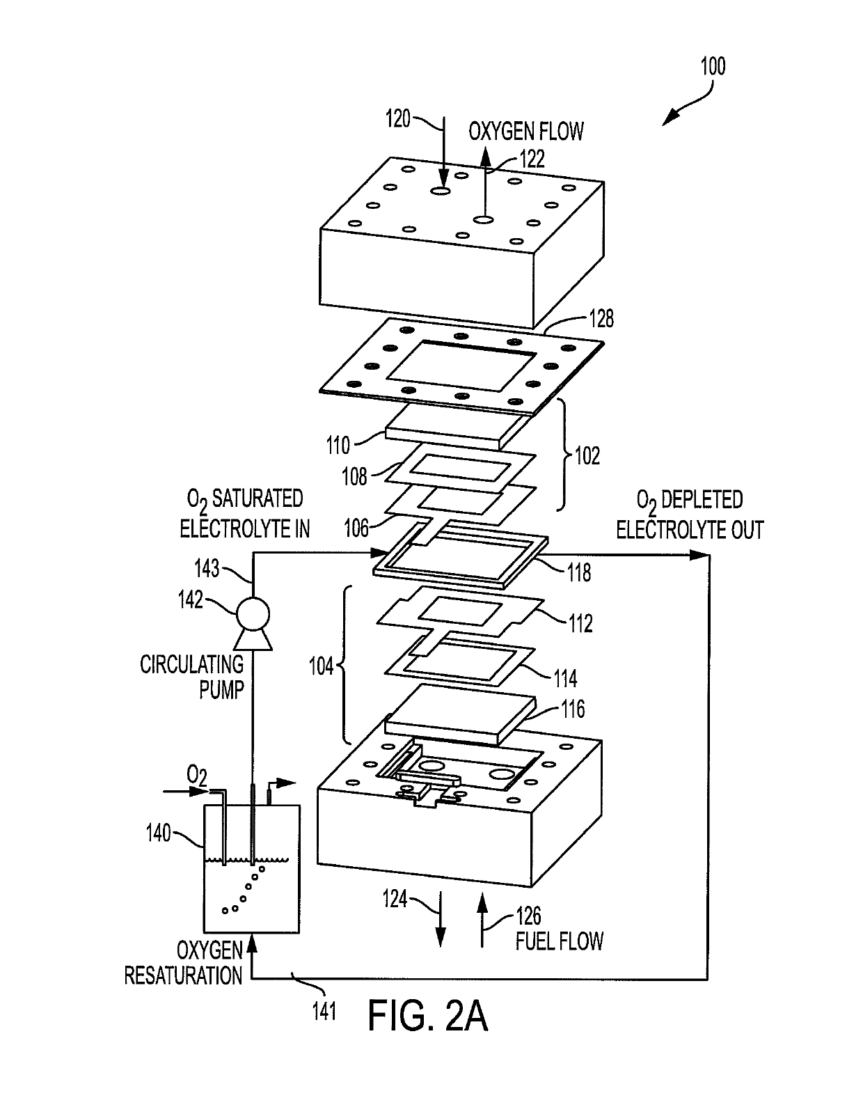
[0054]For example, according to the presently described embodiments, an improved electrochemical fuel cell system is provided by use of flowing electrolyte to maximize fuel cell performance. In at least one form, the flowing electrolyte is first saturated with oxidant (oxygen) either in the molecular (O2) form or in the ionic (oxygen ion such as superoxide, peroxide, oxide) form prior to flowing the electrolyte along the fuel-membrane support interface. In another form, the system uses a dual-porosity structure implementing a gas diffuser / catalyst layer to allow the use of gase...


PUM

PropertyMeasurementUnit
diametersaaaaaaaaaa
thicknessaaaaaaaaaa
diametersaaaaaaaaaa

Abstract

A flowing electrolyte fuel cell system design (DHCFC-Flow) is provided. The use of a flowing oxygen-saturated electrolyte in a fuel cell offers a significant enhancement in the cell performance characteristics. The mass transfer and reaction kinetics of the superoxide / peroxide / oxide ion (mobile oxygen ion species) in the fuel cell are enhanced by recirculating an oxidizing gas-saturated electrolyte. Recirculating oxygen-saturated electrolyte through a liquid channel enhances the maximal current observed in a fuel cell. The use of a oxygen saturated electrolyte ensures that the reaction kinetics of the oxygen reduction reaction are fast and the use of convection ameliorates concentration gradients and the diffusion-limited maximum current density. The superoxide ion is generated in situ by the reduction of the oxygen dissolved in the gaseous electrolyte. Also, a dual porosity membrane allows the uniform flow of fuel (e.g., methane) on the fuel side, without allowing phase mixing. The capillary pressure for liquid intrusion into the gas phase and vice versa is quite large, estimated to be 1-10 psi. This makes it easier to control the fluctuations in gas / liquid velocity which might otherwise lead to phase mixing and the loss of fuel cell performance. In one variation, a dual-porosity membrane structure is incorporated in the system to allow uniform flow of fuel and prevent mixing of fuel with a liquid electrolyte.

Description

[0001]This invention was made with U.S. Government support under government contract DE-AR0000500 awarded by the U.S. Department of Energy (DOE) / ARPA-E under the Reliable Electricity Based on ELectrochemical Systems (REBELS) program. The Government has certain rights in this invention.BACKGROUND[0002]Direct hydrocarbon fuel cells (DHCFCs) offer an environment-friendly method to produce electricity directly from fossil fuels at a higher efficiency than fuel combustion processes without necessitating the use of a reformer to convert the fuel to hydrogen. Conventional proton exchange membrane (PEM) fuel cells require pure hydrogen fuel to generate electricity by the conduction of hydrogen (H+) ions (i.e., protons) across the electrolyte membrane towards the cathode (oxygen side electrode) where they react with the oxygen to complete the electro-chemical circuit. In contrast to this, DHCFCs operate on the principle of conducting oxygen ions across the electrolyte—in the opposite directi...

Claims


Application Information

Patent Timeline
Patent Type & Authority Patents(United States)
IPC IPC(8): H01M8/00H01M4/86H01M8/04276H01M8/023H01M8/22H01M8/18H01M8/2455
CPCH01M4/8626H01M8/023H01M8/04283H01M8/188H01M8/22H01M8/2455Y02E60/50
Inventor DESAI, DIVYARAJVEDHARATHINAM, VEDASRISHERIDAN, MARTIN JOSEPHPATTEKAR, ASHISH V.ELDERSHAW, CRAIGPADMARAJAN, RAJESH KUMARIFTIME, GABRIEL
Owner XEROX CORP
Why Eureka
Try Eureka