Sponge Cleaning and Disinfecting Device

a disinfecting device and sponge technology, applied in the direction of carpet cleaners, cleaning processes and apparatus, cleaning using liquids, etc., can solve the problems of uneven walls and disinfectant solutions in the channel, and achieve the effect of reducing spillage, reducing and reducing the surface tension of liquids

Active Publication Date: 2017-09-07
SPONGEBATH
View PDF0 Cites 0 Cited by
  • Summary
  • Abstract
  • Description
  • Claims
  • Application Information

AI Technical Summary

Benefits of technology

[0007]Removing the sponge from the earlier device caused disinfectant solution to spill. To reduce spillage, we wanted the disinfectant solution to drain more quickly from the sponge.
[0008]Through several experiments, we developed a new shape for the paddles' channels. In our previous device, the channels were circular and kept the same shape from the inside of the paddle to its outside. In our improved device, the channels have a teardrop shape, and the walls of our channels are uneven. That is, in our improved device, the round part of the teardrop channel keeps the same shape from the inside of the paddle to its outside, but the point of the teardrop channel is larger at the outside of the paddle than at its inside. This uneven shape defeats the surface tension of liquids, allowing very little disinfectant solution to remain in the channels when the paddles are removed from the tub.
[0009]The earlier device tipped over too easily, so we developed two new ways to keep the tub upright. The first way is a heavy base. The device user can choose to fasten the heavy base to the bottom of the tub. Like the bottom of the tub, the heavy base has an oval cylindrical shape, but the base is larger than the bottom of the tub, stabilizing the device. Once the base is fastened on, the device stands upright and will not tip over with normal usage.

Problems solved by technology

Removing the sponge from the earlier device caused disinfectant solution to spill.
In our improved device, the channels have a teardrop shape, and the walls of our channels are uneven.

Method used


Image

  • Sponge Cleaning and Disinfecting Device
  • Sponge Cleaning and Disinfecting Device
  • Sponge Cleaning and Disinfecting Device

Examples


Embodiment Construction

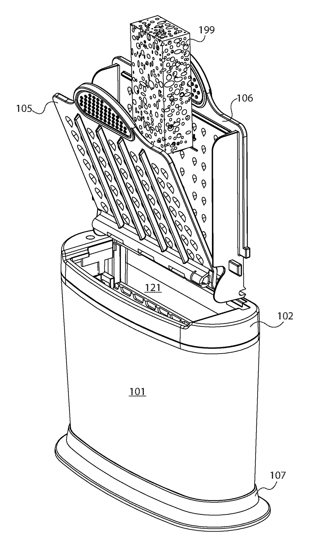
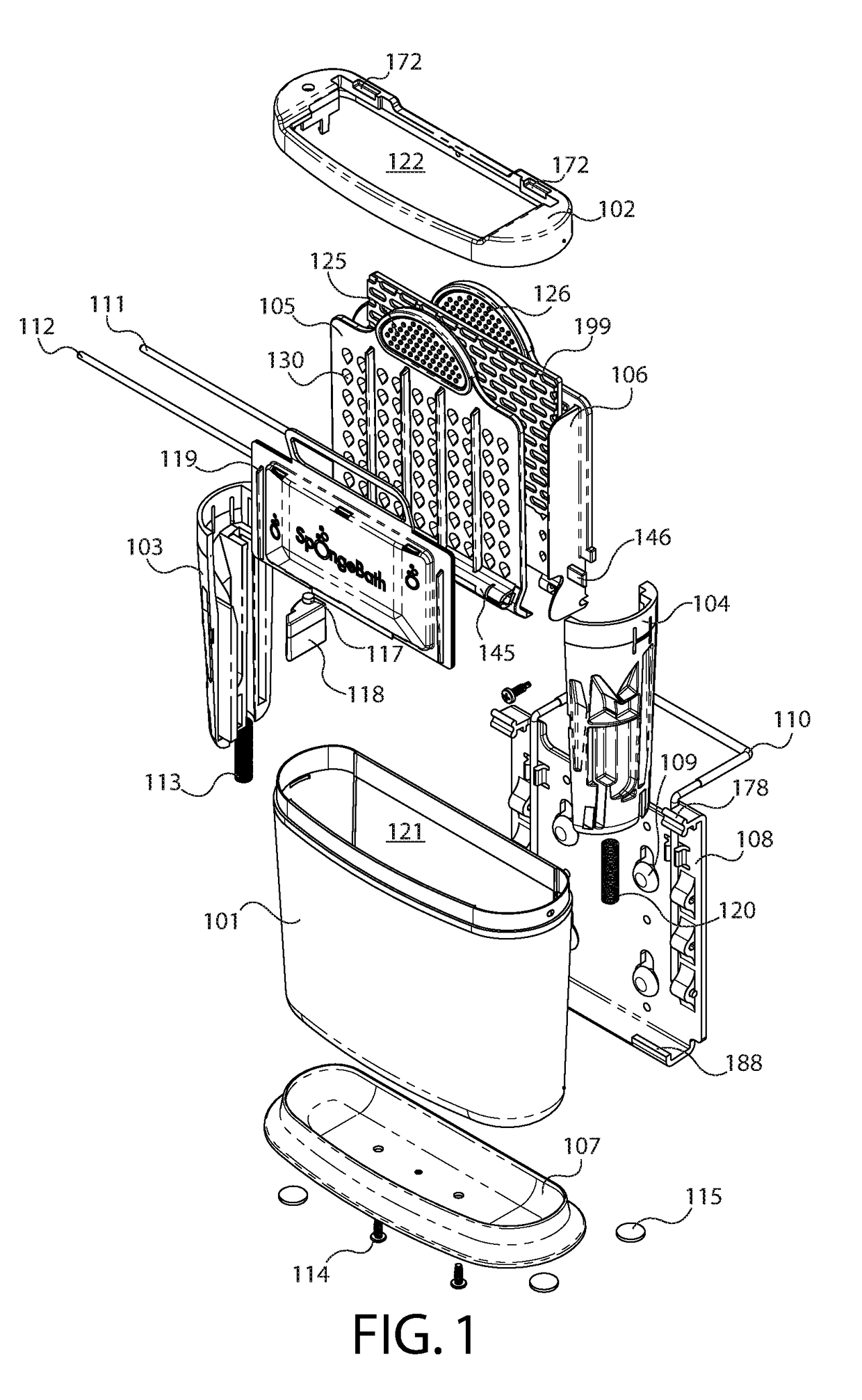
[0116]FIG. 1 is an exploded view of the sponge cleaning and disinfecting device. FIG. 1 shows a hollow tub 101 in which fits a front paddle 105 topped by a front paddle grip 125, a rear paddle 106 topped by a rear paddle grip 126, a removable disinfectant cartridge 119, a left side rail 103, a right side rail 104, a left tub spring 113, a right tub spring 120, a warning light 117, and a warning light control box 118. The cap 102 fits over the top of the hollow tub 101, allowing entry into the cavity 121 of the tub 101 through the cap opening 122. The cap 102 has an attachment divot 172 on each side of its rear. On each side of the rear paddle 106 is a side tab 146. On the front of the front paddle 105 is a front paddle pivot channel 145. Also visible is the paddle connector hinge pin 111 and the front paddle pivot pin 112. Between the front paddle 105 and the rear paddle 106 sits a sponge 199, to illustrate the sponge's 199 relative position to the rest of the device components.

[011...


PUM


Abstract

The device cleans and disinfects sponges. The device has a tub with a cavity of sufficient space to hold paddles for wringing a sponge, a cartridge for holding a slow-dissolving disinfectant, and a sponge. The cavity is filled with a disinfectant solution. The device can be mounted on the inside wall of a sink or cabinet with an included bracket or can be stood in a base on a countertop. The device includes a warning light programmed to remind the user when to change the slow-dissolving disinfectant. The user inserts a sponge between the paddles, inserts the paddles into the cavity, and squeezes the paddles together. The user then releases the paddles, causing the sponge to absorb the disinfectant solution. When the user removes the paddles, specially-designed fluid channels quickly drain the sponge.

Description

CROSS-REFERENCE TO RELATED APPLICATIONS[0001]This application is a national phase application under 35 U.S.C. 371 from International Application PCT / US15 / 50145, filed Sep. 15, 2015, which in turn claims priority to U.S. Provisional Patent Application 62 / 050,560, filed Sep. 15, 2014. The contents of those applications are hereby incorporated by reference.BACKGROUND OF THE INVENTION[0002]It would shock most people to know that the sponge is one of the filthiest, most germ-ridden items in the average home. Bits of food nestled in a damp sponge is the perfect breeding ground for germs. Studies have shown that sponges have more germs than even toilet seats.[0003]Surprised and a little disgusted, we have been working for years on an ideal, convenient solution to clean and disinfect sponges. Several years ago, we created a primitive sponge cleaning and disinfecting device. We filed a U.S. patent application, leading to U.S. Pat. No. 7,892,485.[0004]That primitive device worked but wasn't u...

Claims


Application Information

Patent Timeline
Patent Type & Authority Applications(United States)
IPC IPC(8): A47L13/59B08B3/08
CPCB08B3/08A47L13/59
Inventor MAITLAND, TODFLANNERY, MATTHEWLOGAN, JOSEPH
Owner SPONGEBATH
Why Eureka
Try Eureka