Curved display manufacturing device and curved display manufacturing method

Active Publication Date: 2017-09-07
TOVIS
View PDF11 Cites 10 Cited by
  • Summary
  • Abstract
  • Description
  • Claims
  • Application Information

AI Technical Summary

Benefits of technology

The present invention relates to a display panel that can be bent into a curved shape without getting damaged during bending. This is possible because force is applied uniformly to the entire portion of the display panel. The invention also includes a pressing roller that attaches a curvature maintaining member to the display panel while moving from one end to the other end of the display panel using a spacer. This prevents failure of bonding between the curvature maintaining member and the display panel. The pressing roller presses the curvature maintaining member while being directed in a tangential direction, which prevents the display panel from being damaged due to non-uniform pressing force. The pressing roller is slidably moved in a lateral direction by a sliding mechanism while being pivoted by a roller pivoting mechanism. This eliminates the necessity of placing the pivotal axis of the pressing roller at an apex of a curved surface, which reduces the size of the apparatus.

Problems solved by technology

In the conventional display device manufacturing apparatus, however, the panel member, which has a flat plate shape, is bent during bonding thereof because the bonding is achieved by pressing force of the first and second jigs and, as such, a bonding portion of the panel member may be non-uniformly bonded.
Furthermore, the panel member is bent under the condition that opposite ends thereof are clamped and, as such, pressing force applied to the panel member may be non-uniform.
As a result, the panel member may be damaged.

Method used


Image

  • Curved display manufacturing device and curved display manufacturing method
  • Curved display manufacturing device and curved display manufacturing method
  • Curved display manufacturing device and curved display manufacturing method

Examples


Embodiment Construction

[0039]Hereinafter, preferred embodiments of the present invention will be described in detail with reference to the accompanying drawings.

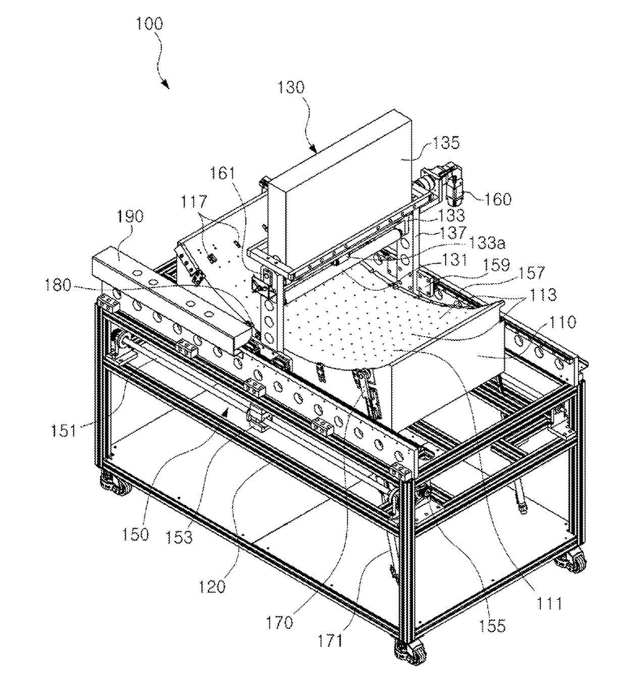
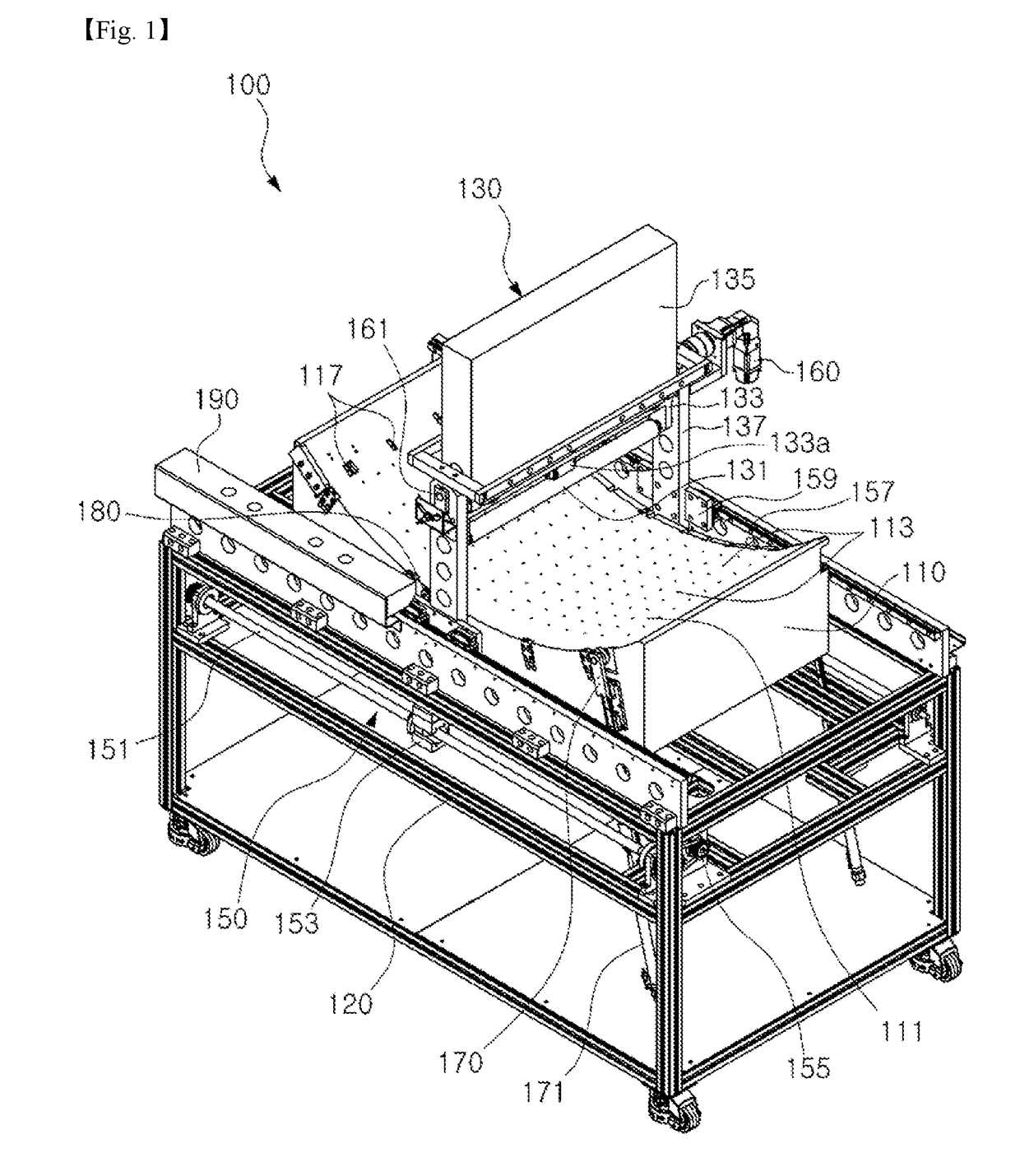
[0040]First, the curved display manufacturing apparatus of the present invention, namely, a curved display manufacturing apparatus 100, is adapted to manufacture a curved display by bending a flat display panel 200, which is pre-fabricated as a ready-made article. The display panel 200, which is to be loaded in the curved display manufacturing apparatus 100, may be shaved to a predetermined thickness so as to be easily bent (FIG. 6).

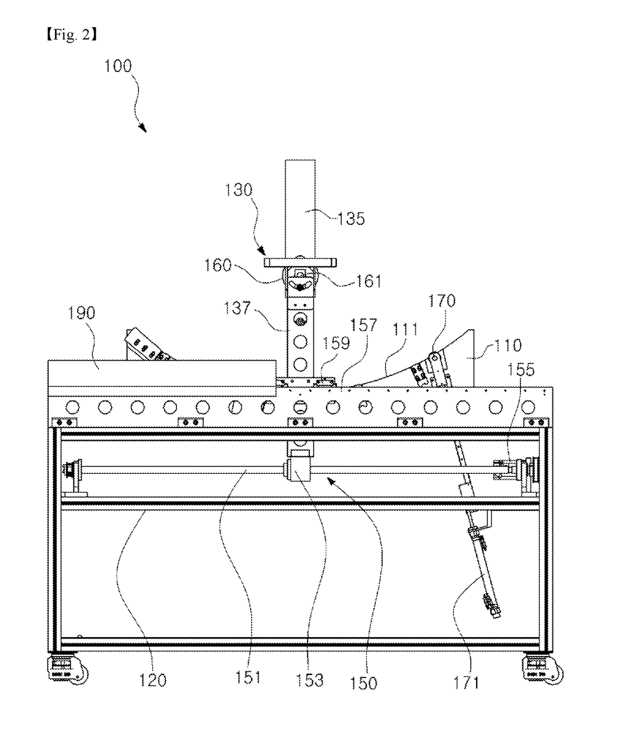
[0041]As illustrated in FIGS. 1 to 5, in accordance with an embodiment of the present invention, the curved display manufacturing apparatus 100 may include a curved surface suction mold 110. The curved surface suction mold 110 may bend the display panel 200, which has a flat plate shape, into a curved shape.

[0042]Meanwhile, the curved suction mold 110 may have a box or block shape. The curved suction mold 110 has an up...


PUM


Abstract

Disclosed are a curved display manufacturing apparatus, comprising: a curved surface suction mold comprising a panel seat surface having a curved shape corresponding to a curved shape of the curved display to be formed, and air sucking holes formed through the panel seat surface; an air sucking unit for sucking air through the air sucking holes; a main frame for supporting the curved surface suction mold, to space the curved surface suction mold from a bottom of the main frame; and a pressing roller unit for pressing a curvature maintaining member to maintain the display panel in a bent state while sliding along a curved surface of the display panel under a condition that the curvature maintaining member overlaps with the display panel, for pressed attachment of the curvature maintaining member to the display panel.

Description

TECHNICAL FIELD[0001]The present invention relates to a curved display manufacturing apparatus and a curved display manufacturing method for manufacturing a curved display, using a pre-fabricated flat display panel.BACKGROUND ART[0002]Recently, in accordance with increased utility of displays and advance of technologies relevant to displays, a curved display, which does not have a flat shape, has been developed.[0003]Such a curved display may be manufactured using, for example, a manufacturing apparatus disclosed in Korean Unexamined Patent Publication No. 10-2014-0010919 (issued on Jan. 27, 2014).[0004]The above-mentioned conventional display device manufacturing apparatus includes a first jig formed with a seat surface to be engaged with one surface of a cover window having a flat portion with opposite curved ends, a second jig disposed spaced apart from the first jig by a certain distance, a clamping member disposed to be spaced apart from at least one of the first and second jig...

Claims


Application Information

Patent Timeline
IPC IPC(8): G02F1/13G09F9/35G02F1/1333G09F9/30
CPCG02F1/1303G09F9/301G02F1/133528G02F1/133305G02F2001/133354G09F9/35G09F9/00G02F1/133325G02F1/133354
Inventor KIM, HWAN JINOH, CHANG MINEOM, GI YUN
Owner TOVIS
Why Eureka
Try Eureka