Lighting apparatus

Inactive Publication Date: 2017-09-07
PANASONIC INTELLECTUAL PROPERTY MANAGEMENT CO LTD
View PDF9 Cites 3 Cited by
  • Summary
  • Abstract
  • Description
  • Claims
  • Application Information

AI Technical Summary

Benefits of technology

[0008]Taking (b) into consideration, there is also a method of adjusting a color-variable wall in order to reduce intraocular scattering due to ambient light, as disclosed in Japanese Unexamined Patent Application Publication No. 2005-302500.
[0009]Here, there has been a demand for a lighting apparatus which allows middle and older aged people to perceive highly vivid colors while avoiding glare.
[0010]Accordingly, the present disclosure provides a lighting apparatus which prevents letters and objects that middle and older aged people observe from appearing to have lower color saturation.
[0011]A lighting apparatus according to an aspect of the present disclosure includes: first light emitting elements; and second light emitting elements having chromaticity values in a same chromaticity range as the first light emitting elements, wherein a spectral distribution of light emitted by the first light emitting elements includes a first peak wavelength in a ra

Problems solved by technology

In particular, improvement in visual environ

Method used


Image

  • Lighting apparatus
  • Lighting apparatus
  • Lighting apparatus

Examples


embodiment 1

[Entire Configuration]

[0034]The following describes a lighting apparatus according to Embodiment 1.

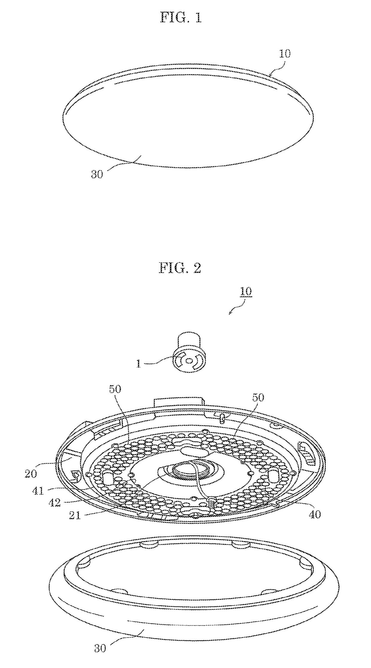
[0035]FIG. 1 is a perspective view illustrating a schematic structure of the lighting apparatus according to Embodiment 1. FIG. 2 is an exploded perspective view illustrating a schematic structure of the lighting apparatus according to Embodiment 1.

[0036]As illustrated in FIGS. 1 and 2, lighting apparatus 10 includes device body 20, cover 30, and light emitter 40. Lighting apparatus 10 is detachably attached to, for example, hook ceiling body 1 provided on the ceiling of a building such as a house, for example.

[0037]Device body 20 is a casing for supporting cover 30 and light emitter 40. Device body 20 is formed in a ring shape having circular opening 21 in the center portion. Hook ceiling body 1 is connected to light emitter 40 through opening 21.

[0038]Note that device body 20 is formed in the stated shape by performing press working on sheet metal such as an aluminum plate or a steel...

verification experiment

[Verification Experiment]

[0068]The inventors examined, by the experiment, influence given by FCI percentages on how colors appear to viewers.

[0069]The summary of the experiment is as follows.

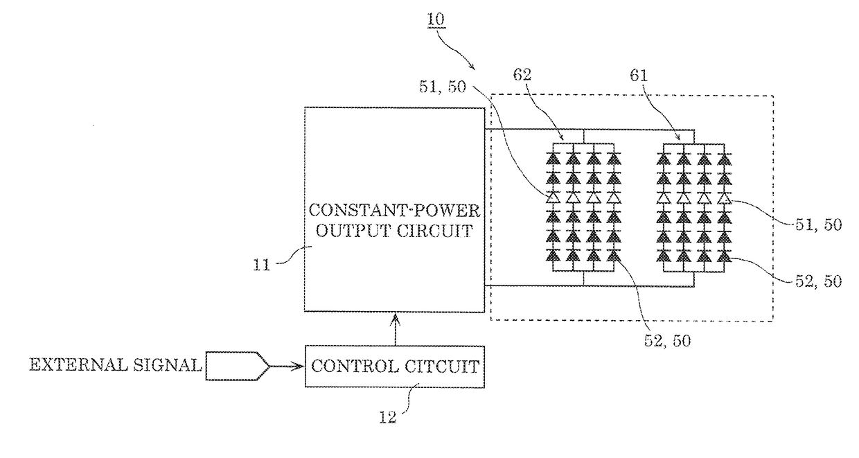
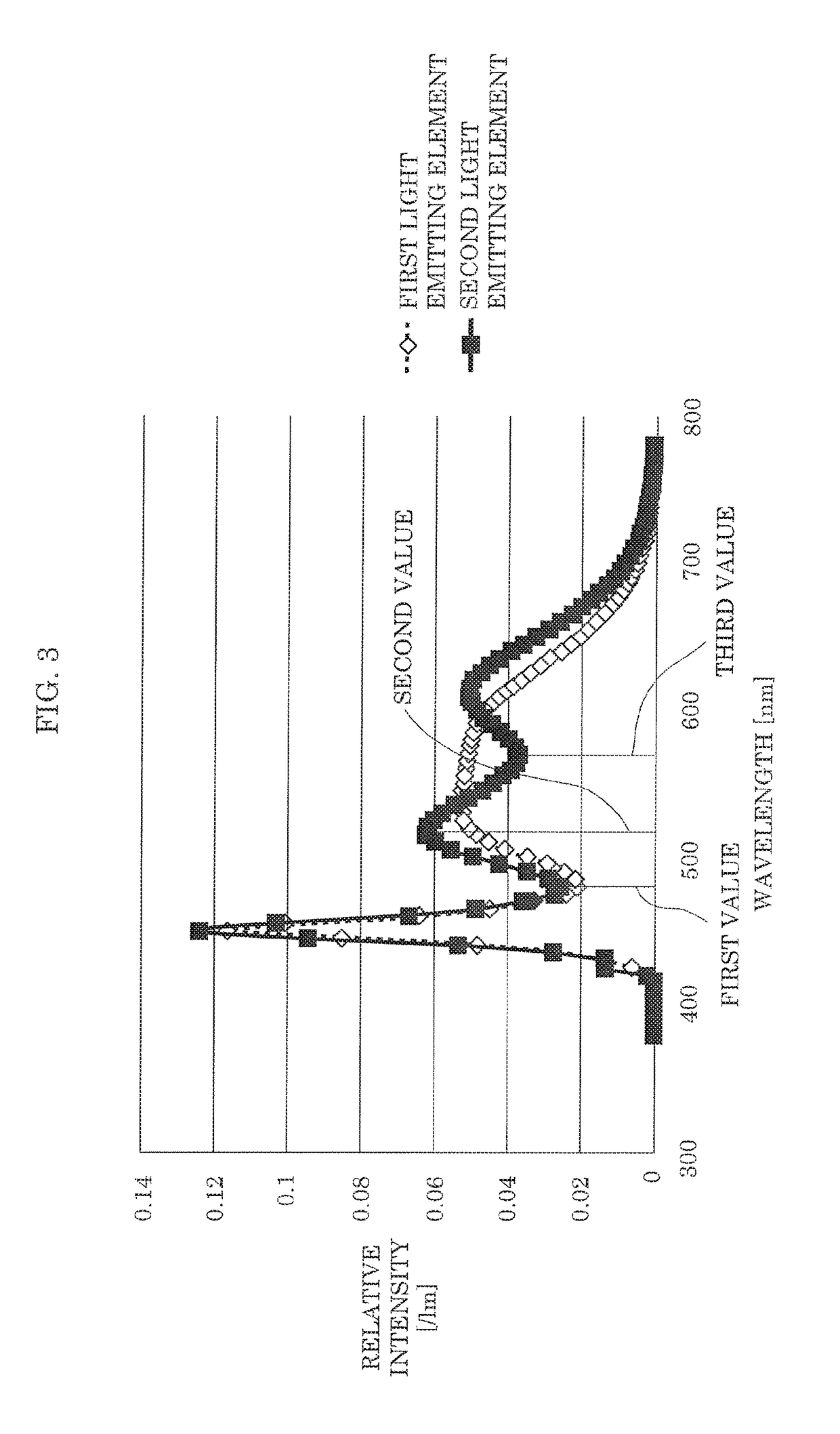
[0070]The color of reference light (correlated color temperature: 6200 K) was adjusted by mixing light emitted by highly efficient first light emitting elements 51 having a high color temperature (correlated color temperature: 6300 K) and light emitted by highly efficient light emitting elements (third light emitting elements) having a low color temperature (correlated color temperature: 2400 K). Three types of test light were adjusted to have 6200 K by changing the ratio of first light emitting elements 51 to high color rendering second light emitting elements 52 having a high color temperature (correlated color temperature: 6500 K) and further adding third light emitting elements. Specifically, test 1 light was adjusted to have 6200 K by adding the third light emitting elements to a group of o...

embodiment 2

[0094]The following describes Embodiment 2. Note that in the following description, the same element as the above embodiment may be given the same numeral, and a description of the element may be omitted.

[0095]Embodiment 1 has described an example in which lighting apparatus 10 which includes first light emitting elements 51 and second light emitting elements 52, whereas Embodiment 2 describes lighting apparatus 10A which includes third light emitting elements 53, in addition to first light emitting elements 51 and second light emitting elements 52.

[0096]FIG. 16 is a schematic diagram illustrating an example of arrangement of first light emitting elements 51, second light emitting elements 52, and third light emitting elements 53 according to Embodiment 2.

[0097]As illustrated in FIG. 16, first light emitting elements 51, second light emitting elements 52, and third light emitting elements 53 are arranged on substrate 41 in triple rings. Here, in the innermost ring, 8 first light emi...


PUM


Abstract

A lighting apparatus includes first light emitting elements and second light emitting elements having chromaticity values in a same chromaticity range. A ratio of a greatest value of a spectral distribution of combined light in a range of 500 nm to 560 nm inclusive to a smallest value of the spectral distribution of the combined light in a range of 500 nm to 650 nm inclusive is 0.85 or less. The combined light is a combination of light emitted by the first light emitting elements and light emitted by the second light emitting elements.

Description

CROSS REFERENCE TO RELATED APPLICATION[0001]This application claims the benefit of priority of Japanese Patent Application Number 2016-041484 filed on Mar. 3, 2016, the entire content of which is hereby incorporated by reference.BACKGROUND[0002]1. Technical Field[0003]The present disclosure relates to a lighting apparatus, and in particular to a lighting apparatus for correcting a change in visual performance due to aging.[0004]2. Description of the Related Art[0005]According to the arrival of an aging society, there has been a great demand for a comfortable environment for middle and older aged people. In particular, improvement in visual environment achieved by lighting is an urgent issue. It is thus necessary to clarify how lighting can correct a change in human visual system caused by aging. Examples of a change in visual performance due to aging mainly include (a) a fall in transmittance of a crystalline lens, in particular a fall in transmittance of a crystalline lens in a sho...

Claims


Application Information

Patent Timeline
IPC IPC(8): H05B33/08F21V23/02F21V3/00H05B44/00
CPCH05B33/0857F21V3/00F21Y2115/10H05B33/0821F21Y2105/18F21V23/02F21S8/04F21V3/02F21V21/03F21V23/003F21Y2113/13H05B45/20H05B45/40
Inventor MATSUBAYASHI, YOKOHIMENO, TOHRUKOIWA, HIROKOTAKEI, NAOKOYAMADA, MAKOTO
Owner PANASONIC INTELLECTUAL PROPERTY MANAGEMENT CO LTD
Why Eureka
Try Eureka