Supercharge Your Innovation With Domain-Expert AI Agents!

Plug-in connector

Active Publication Date: 2017-09-14
KRONENBERG RALF M
View PDF4 Cites 0 Cited by
  • Summary
  • Abstract
  • Description
  • Claims
  • Application Information

AI Technical Summary

Benefits of technology

This patent describes a connector for joining hollow sections together that has resilient retaining elements that can be positioned over a wide part of the connector. These resilient elements compensate for any variation in the size of the hollow section and allow the connector to maintain a secure and tight connection without damaging the hollow section. The retaining elements at the bottom of the connector make good contact with the hollow section and prevent any flow of granules between the sections. The connector also has a central stop that helps ensure accurate positioning of the ends of the hollow sections and prevents the formation of gaps or escape of granules at the connection point. Overall, this connector design provides a reliable and effective connection for joining hollow sections.

Problems solved by technology

These plug-in connectors are less suited for more labile hollow sections made of plastic or from a combination of plastic and metal.

Method used


Image

  • Plug-in connector
  • Plug-in connector
  • Plug-in connector

Examples


Embodiment Construction

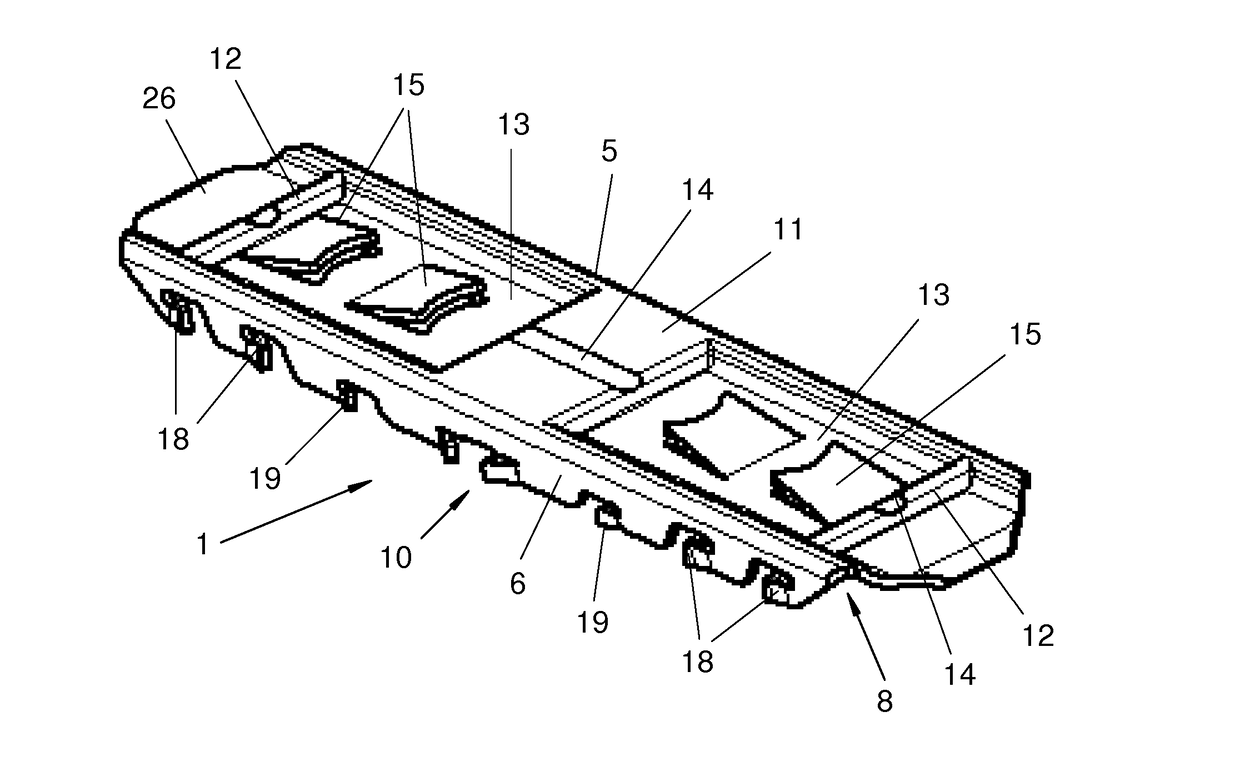
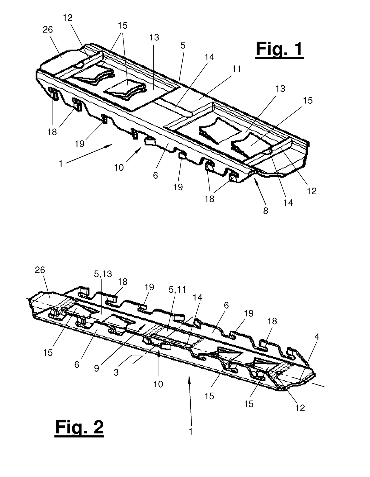
[0025]Referring to the drawings, the present invention pertains to a plug-in connector (1) for hollow sections or hollow section ends (2) of a spacer for insulating glazing. The present invention pertains, in addition, to a plug-in connection comprising a plug-in connector (1) and plugged-in hollow section ends (2).

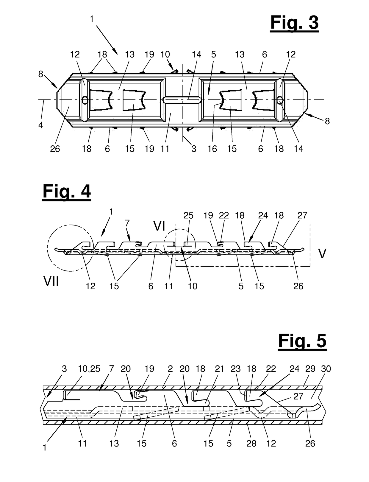
[0026]FIGS. 1 through 4 show the plug-in connector (1) in different views. FIG. 5 shows the plug-in position of the plug-in connector (1) into a hollow section end (2) on one side.

[0027]The plug-in connector (1) is configured as a straight connector in the embodiments shown. As an alternative, it may be configured as a corner angle. The plug-in connector (1) has a center (3) and connector legs projecting therefrom in different directions. The connector legs are flush in the straight connector being shown. In a corner angle, they form an angle differing from 180° , e.g., an angle of 90° . The plug-in connector (1) has, in addition, a longitudinal axis (4), which extends al...


PUM


Abstract

A plug-in connector (1), for warm edge hollow profiles (2) of spacers of insulating glazing, has a base with side walls (6) at the edges. A plurality of retaining elements (15) formed as spring lugs are arranged on the outer side of the base (bottom) (5) in a single central row on each of both sides of the center (3) of the plug-in connector (1). Starting from the base (5), the retaining elements are directed obliquely outwards towards the adjacent hollow profile base (28) and towards the connector center (3). The retaining elements (15) are in each case arranged in a sunken base region (13) on the outer side of the base (5) that adjoins a raised, plate-like base region (11) arranged in the region of the center (3). Laterally obliquely outwardly directed resilient retaining elements (18,19) are arranged at the free edge region (7) of the side walls (6).

Description

CROSS REFERENCE TO RELATED APPLICATIONS[0001]This application is a United States National Phase Application of International Application PCT / EP2015 / 070438, filed Sep. 8, 2015, and claims the benefit of priority under 35 U.S.C. §119 of German Application 20 2014 104 222.9, filed Sep. 8, 2014, the entire contents of which are incorporated herein by reference.FIELD OF THE INVENTION[0002]The present invention pertains to a plug-in connector for hollow sections, especially warm-edge hollow sections, of spacers of an insulating glazing, wherein the plug-in connector has a bottom (base) with side walls at the edges.BACKGROUND OF THE INVENTION[0003]Plug-in connectors for hollow sections of spacer frames for insulating glazing are known from practice in various embodiments. These plug-in connectors are designed, as a rule, for mechanically stable hollow sections made of metal. These are, e.g., extruded sections made of light metal or rolled sections or sections manufactured in another manner...

Claims


Application Information

Patent Timeline
IPC IPC(8): E06B3/667E06B3/663
CPCE06B3/66314E06B3/667
Inventor KRONENBERG, RALF M.
Owner KRONENBERG RALF M
Features
  • R&D
  • Intellectual Property
  • Life Sciences
  • Materials
  • Tech Scout
  • Unparalleled Data Quality
  • Higher Quality Content
  • 60% Fewer Hallucinations
Learn More