Unlock instant, AI-driven research and patent intelligence for your innovation.
Microphone array, monitoring system, and sound pickup setting method
Active Publication Date: 2017-09-14
PANASONIC INTELLECTUAL PROPERTY MANAGEMENT CO LTD
View PDF3 Cites 36 Cited by
Summary
Abstract
Description
Claims
Application Information
AI Technical Summary
This helps you quickly interpret patents by identifying the three key elements:
Problems solved by technology
Method used
Benefits of technology
Benefits of technology
[0022]According to the present disclosure, an amount of work for installation can be reduced when a monitoring system is set up in a state of being combined with a camera. Additionally, according to the present disclosure, an amount of work for installation can be reduced when a monitoring system
Problems solved by technology
However, in monitoring of only a picture, because there is necessarily a limitation on an amount of information that is acquired, there is an increasing demand for a monitoring system that can obtain voice data in order to perform monitoring that uses voice.
However, in most cases, the microphone that is used in this product is non-directional, and for example, although the microphone is unidirectional, this directional characteristic is a wide angle.
Thus, work for the additional installation is difficult.
In this manner, in a case where later add
Method used
Image
Click on the blue label to locate the original text in one second.
Reading with bidirectional positioning of images and text.
Examples
first embodiment
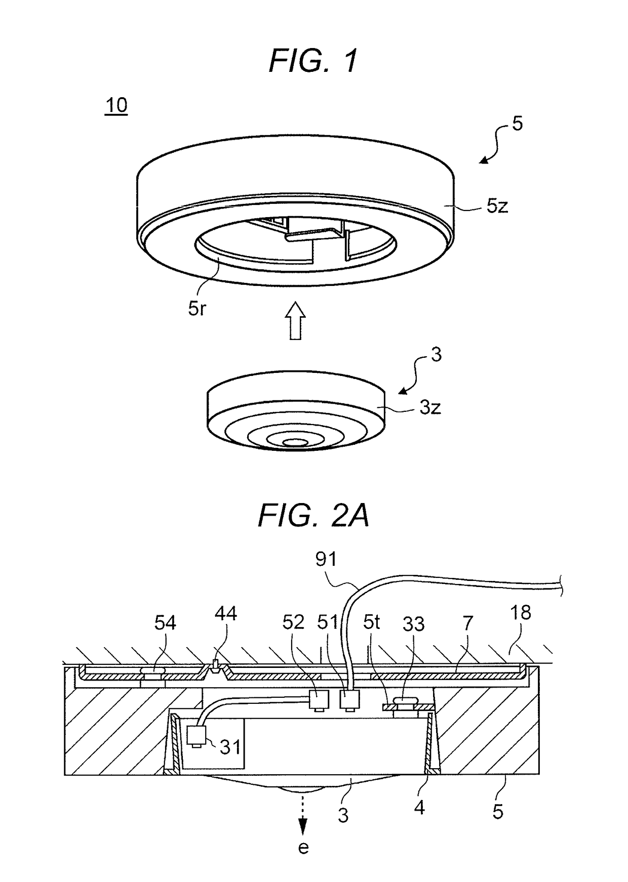
[0069]FIG. 1 is a diagram illustrating an external appearance of monitoring system 10 according to a first embodiment. Monitoring system 10 has a configuration in which network-supporting type camera 3 and microphone array 5 are combined.
[0070]Camera 3 is an omnidirectional camera (that is, a camera that has a view angle in an image capture range of 360 degrees) that has a disc-shaped case 3z and is equipped with a fish-eye lens on the front surface of case 3z. Microphone array 5 has a ring-type case 5z in which a plurality of microphone units 65 (refer to FIG. 4) are concentrically arranged, and picks up voice in all directions (that is, at an angle of 360 degrees).
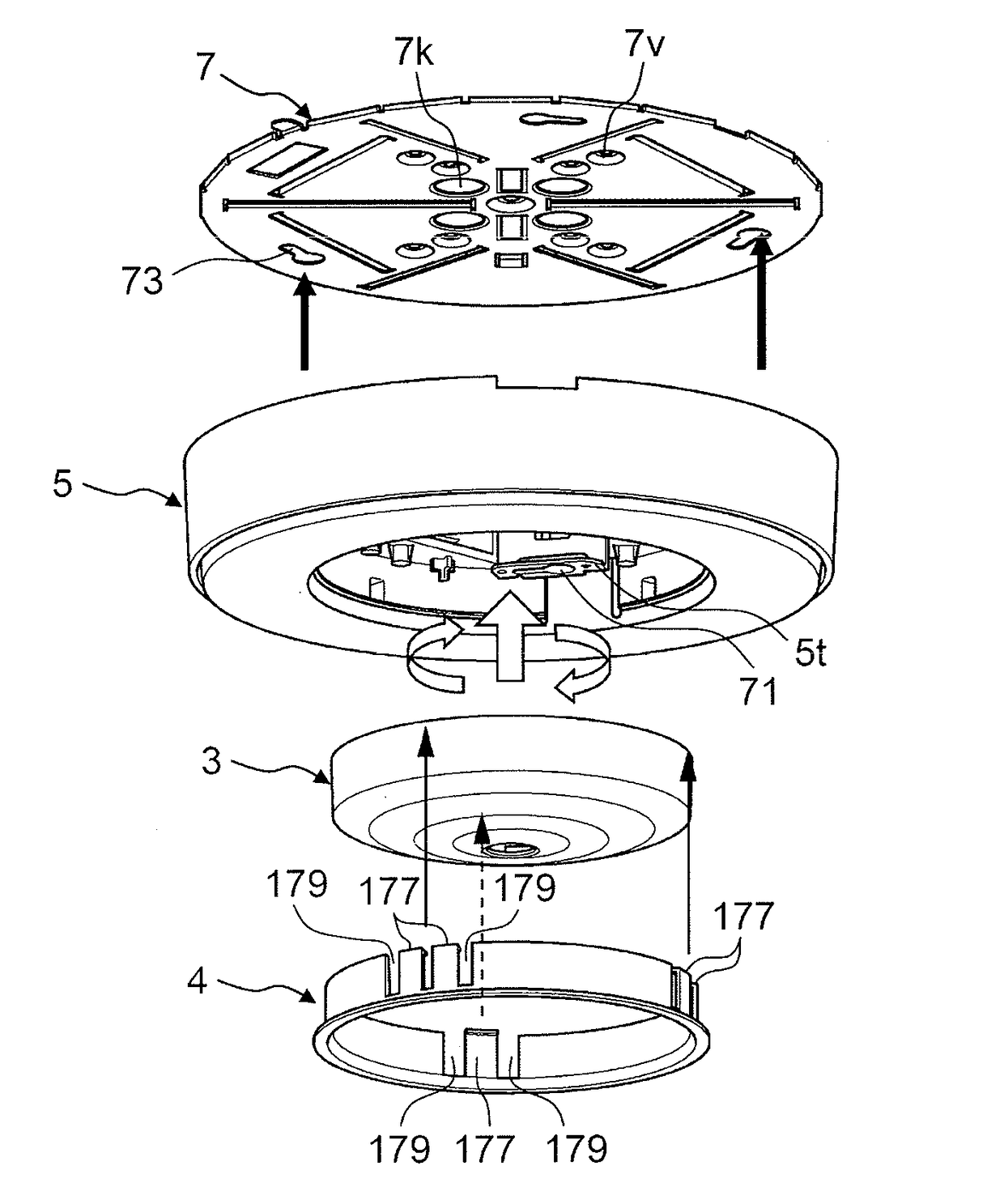
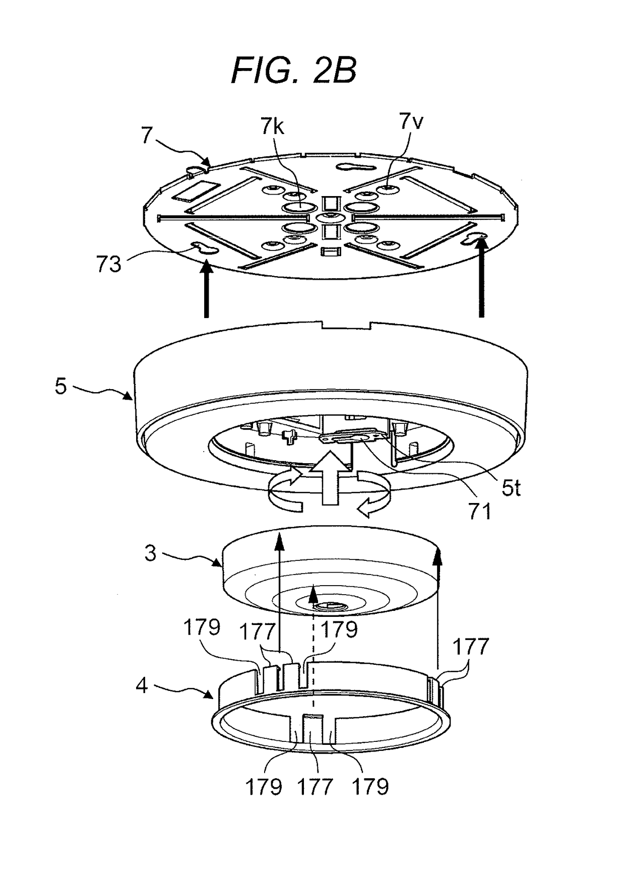
[0071]Monitoring system 10 is installed on ceiling 18 (refer to FIG. 2) in a state where case 3z of camera 3 is accommodated into opening 5r that is formed in case 5z of microphone array 5.
[0072]FIG. 2A is a cross-sectional diagram illustrating a structure in a state where monitoring system 10 that is configured with cam...
second embodiment
[0132]In the first embodiment described above, the case is described where microphone array 5 that has ring-type case 5z is attached to ceiling attachment metal fitting 7 in such a manner as to externally fit camera 3 that has disc-shaped case 3z, but in a second embodiment, a case is described where the microphone array is installed on the ceiling in a state of being positioned a distance away from the camera.
[0133]FIGS. 9A and 9B are diagrams illustrating a configuration of monitoring system 10A according to the second embodiment. FIG. 9A is a diagram illustrating an installed state of camera 3A and microphone array 5A that are installed on ceiling 18. FIG. 9B is a perspective diagram illustrating an external appearance of microphone array 5A.
[0134]Monitoring system 10A according to the second embodiment has almost the same configuration as monitoring system 10 according to the first embodiment. Constituent elements that are the same as those in the first embodiment, which are des...
third embodiment
[0144]In the first and second embodiments describe above, the monitoring system that is configured with the microphone array and the camera is installed on the surface of the ceiling, but in a third embodiment, a ceiling-embedded monitoring system is described.
[0145]FIG. 10A is a cross-sectional diagram illustrating an attachment structure of ceiling-embedded monitoring system 10B according to the third embodiment. Concrete ceiling building frame 19, which is one portion of a building, is provided on the rear side of ceiling 18. Fixation bolt 19z is fixed in such a manner that fixation bolt 19z protrudes from ceiling building frame 19 toward the ceiling 18 side. As will be described below, plate-shaped protrusion member 7m that is one portion of attachment metal fitting 7C is inserted between a pair of nuts 19y that are engaged with fixation bolt 19z, and thus attachment metal fitting 7C is fixed by fixation bolt 19z in a suspended state.
[0146]FIG. 11 is a perspective diagram illust...
PUM
Abstract
When a microphone array apparatus sound-picks up voice in a prescribed sound volume or higher, which is output from a sound source, and sends voice data on the voice to voice processing apparatus, a sound source direction detection unit causes sound source marks, each of which indicates a directivity direction, to be displayed on a display, and urges a user to make a selection among the sound source marks and to input camera information. A voice processing apparatus transmits the camera information that is input, and the directivity direction, to the microphone array apparatus. The microphone array apparatus stores the camera information and the directivity direction, as a preset information table, in a storage unit. Accordingly, where a positional relationship between the camera and the microphone array is unclear, directionality is formed in a determined image capture position, and voice in the predetermined image capture position is output clearly.
Description
TECHNICAL FIELD[0001]The present disclosure relates to a microphone array, a sound pickup system and a sound pickup setting method, in which directionality for voice that is sound-picked up is formed in a predetermined position and is output.BACKGROUND ART[0002]In a monitoring system that is installed in a prescribed position (for example, a ceiling or a wall) within a factory, a store (for example, a retail store or a bank), a shopping center, and a public place (for example, a station or a library), a plurality of camera apparatuses are connected through a network, and monitoring of picture data (which, hereinafter, includes a still image and a moving image) in a prescribed range for a monitoring target is performed in a monitoring apparatus that is installed in one place.[0003]However, in monitoring of only a picture, because there is necessarily a limitation on an amount of information that is acquired, there is an increasing demand for a monitoring system that can obtain voice ...
Claims
Application Information
Patent Timeline
Application Date:The date an application was filed.
Publication Date:The date a patent or application was officially published.
First Publication Date:The earliest publication date of a patent with the same application number.
Issue Date:Publication date of the patent grant document.
PCT Entry Date:The Entry date of PCT National Phase.
Estimated Expiry Date:The statutory expiry date of a patent right according to the Patent Law, and it is the longest term of protection that the patent right can achieve without the termination of the patent right due to other reasons(Term extension factor has been taken into account ).
Invalid Date:Actual expiry date is based on effective date or publication date of legal transaction data of invalid patent.
