
Clipwave System

Active Publication Date: 2017-09-21
BAYERISCHE MOTOREN WERKE AG
View PDF2 Cites 1 Cited by
  • Summary
  • Abstract
  • Description
  • Claims
  • Application Information

AI Technical Summary

Benefits of technology

[0006]This measure makes it possible for the welding beads to enter into the recesses in the bearing shoulder, with the result that the bearing face of the underhead can come into contact on the corresponding face. In alternative embodiments, the recesses can be of su

Problems solved by technology

As a result, the fastening quality is reduced because the

Method used


Image

  • Clipwave System
  • Clipwave System
  • Clipwave System

Examples


Example

DETAILED DESCRIPTION OF THE DRAWINGS

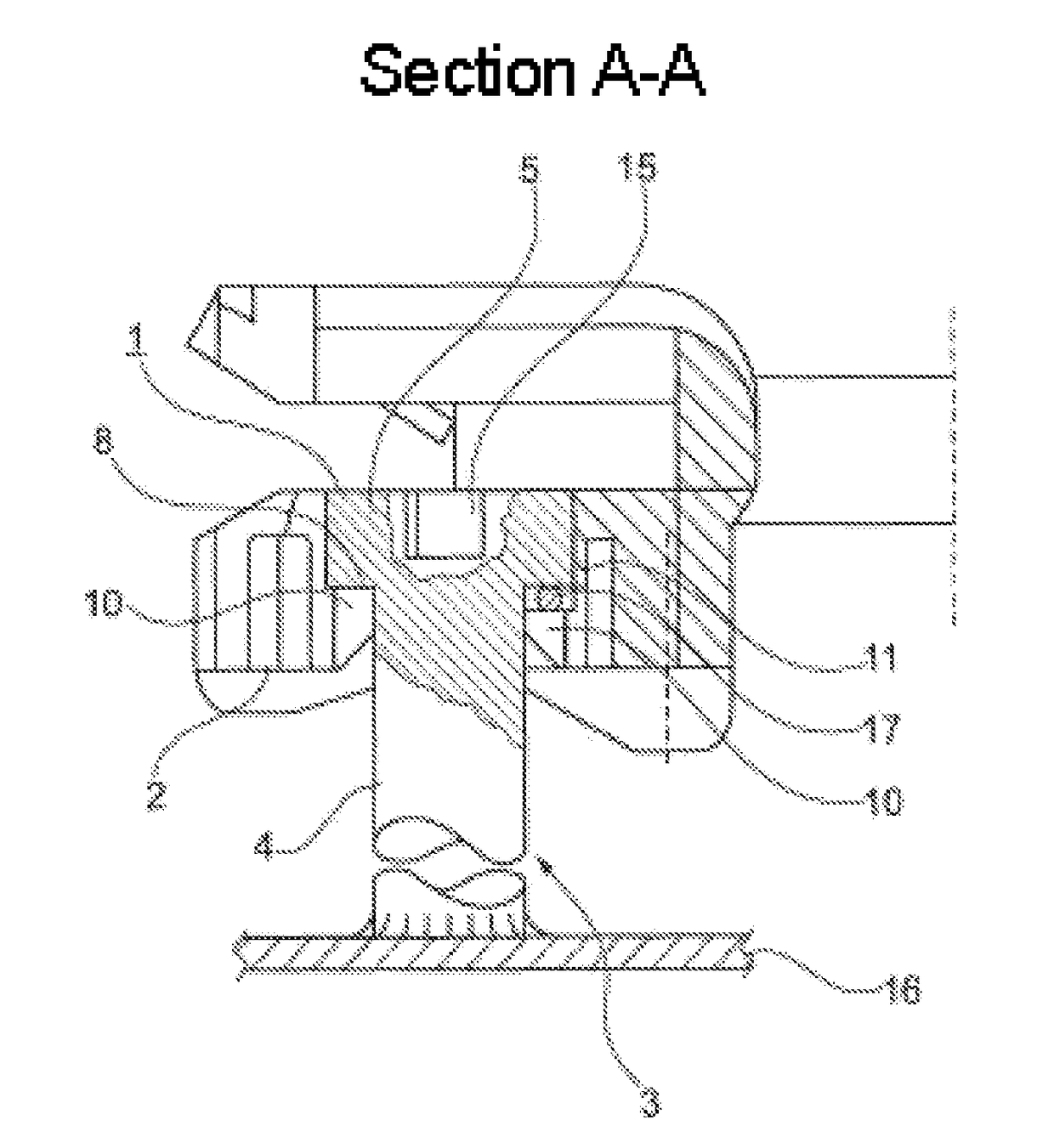
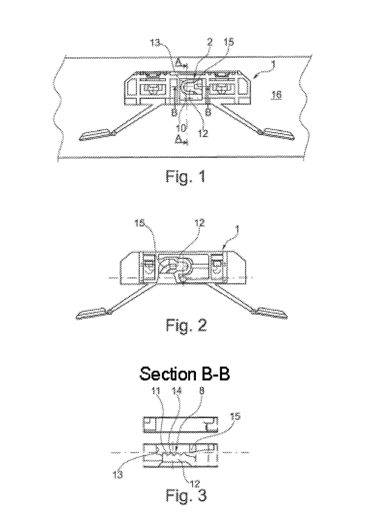
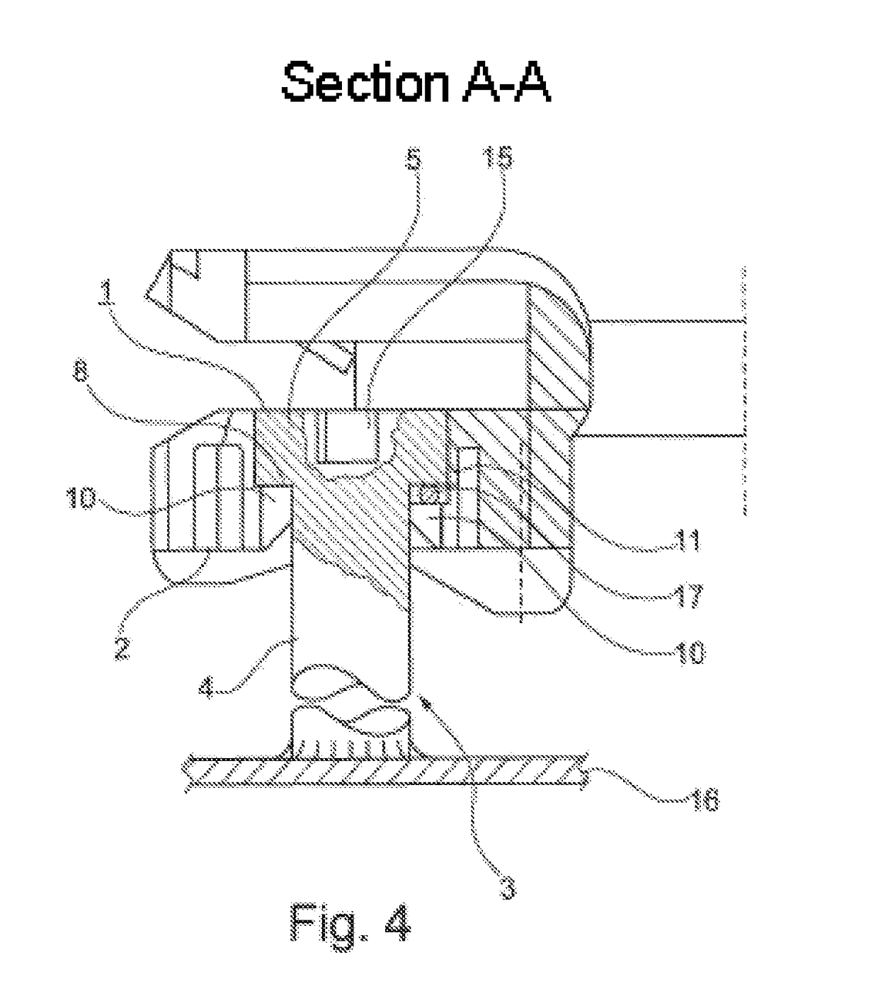
[0018]FIG. 1 shows a view from the front of a retaining element 1 having a retaining device 2. The retaining element 1 is held by a T stud 3 (cf. FIG. 4) and serves to block a component which can be a structural element of a motor vehicle, for example a rail or trim part. As can be seen from FIG. 5, the retaining device 2 which is configured on the retaining element has a bottom wall 9, in which a U-shaped passage 12 with a circumferential side wall 13 is formed. In the exemplary embodiment which is shown, the retaining device 2 is arranged in a somewhat depressed manner on the retaining element. Here, a bearing shoulder 10 which is provided with recesses and protrudes radially inward is configured on the side wall 13 approximately halfway up the height of the wall. The bearing shoulder 10 has a corresponding face 8, onto which the underhead 6 of a stud head 5 of the T stud 3 can come into contact, cf. FIGS. 7A and 7B.

[0019]The T studs 3 are welde...


PUM


Abstract

An arrangement is provided for fastening a structural element, which has a retaining device that interacts with a T-stud, wherein the T-stud has a stud shaft and a stud head with an underhead having a contact surface for contacting at least one counter-surface formed on the retaining device. The stud shaft can be welded to a component. The at least one counter-surface of the retaining device is designed on a contact shoulder for the underhead of the stud head which encompasses the stud at least in part. A plurality of recesses are designed in the contact shoulder of the retaining apparatus, interrupting the counter-surface, wherein the contact surface of the underhead contacts the contact shoulder of the retaining apparatus in the plane of the countersurface.

Description

CROSS REFERENCE TO RELATED APPLICATIONS[0001]This application is a continuation of PCT International Application No. PCT / EP2015 / 074244, filed Oct. 20, 2015, which claims priority under 35 U.S.C. §119 from German Patent Application No. 10 2014 224 929.5, filed Dec. 4, 2014, the entire disclosures of which are herein expressly incorporated by reference.BACKGROUND AND SUMMARY OF THE INVENTION[0002]The invention relates to an arrangement for fastening a retaining element which consists of plastic to a metal surface, having a retaining device which interacts with a T stud, step stud or the like. The T stud has a stud shank and a stud head with an underhead with a bearing face for bearing on at least one corresponding face which is formed on the retaining device. It is possible for the stud shank to be welded to a metal surface, and the at least one corresponding face of the retaining device is configured on at least one bearing shoulder for the underhead of the stud head, which bearing s...

Claims


Application Information

Patent Timeline
IPC IPC(8): F16B21/09B60R13/02F16B5/06
CPCF16B21/09B60R13/0206F16B5/0657
Inventor KRIPPL, HERMANNBASKAYA, TUBA
Owner BAYERISCHE MOTOREN WERKE AG
Learn More