Mandrel structure and manufacturing method thereof

Active Publication Date: 2020-07-23
HONDA MOTOR CO LTD
View PDF0 Cites 0 Cited by
  • Summary
  • Abstract
  • Description
  • Claims
  • Application Information

AI Technical Summary

Benefits of technology

The present invention aims to provide a mandrel structure that allows fittings to be accurately and reliably positioned relative to the mandrel. The technical effect of this invention is to provide a reliable and accurate method of manufacturing a mandrel structure.

Problems solved by technology

When the fittings are not securely fixed to the mandrel, the surrounding reinforcing fibers are disturbed so that the completed pressure vessel may be flawed.

Method used


Image

  • Mandrel structure and manufacturing method thereof
  • Mandrel structure and manufacturing method thereof
  • Mandrel structure and manufacturing method thereof

Examples


Embodiment Construction

)

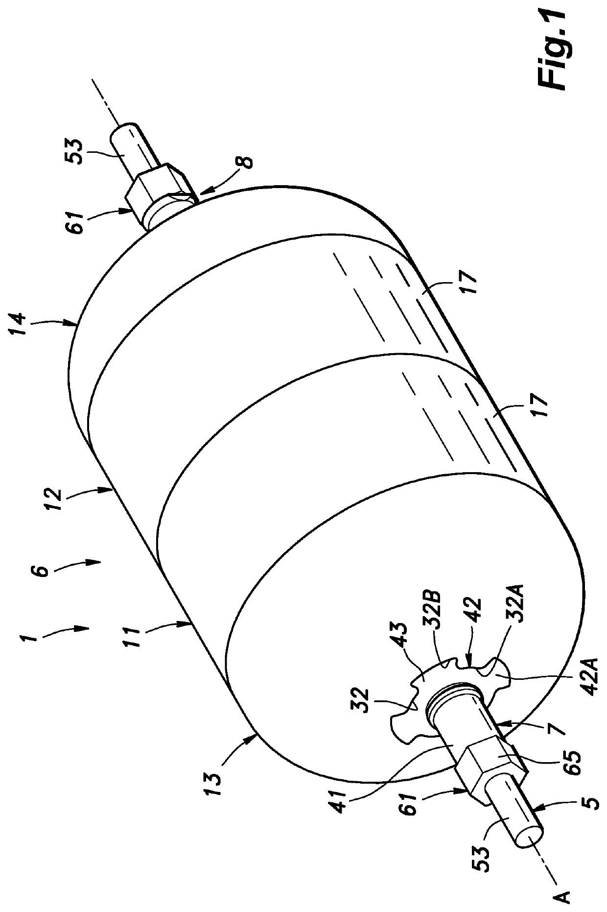
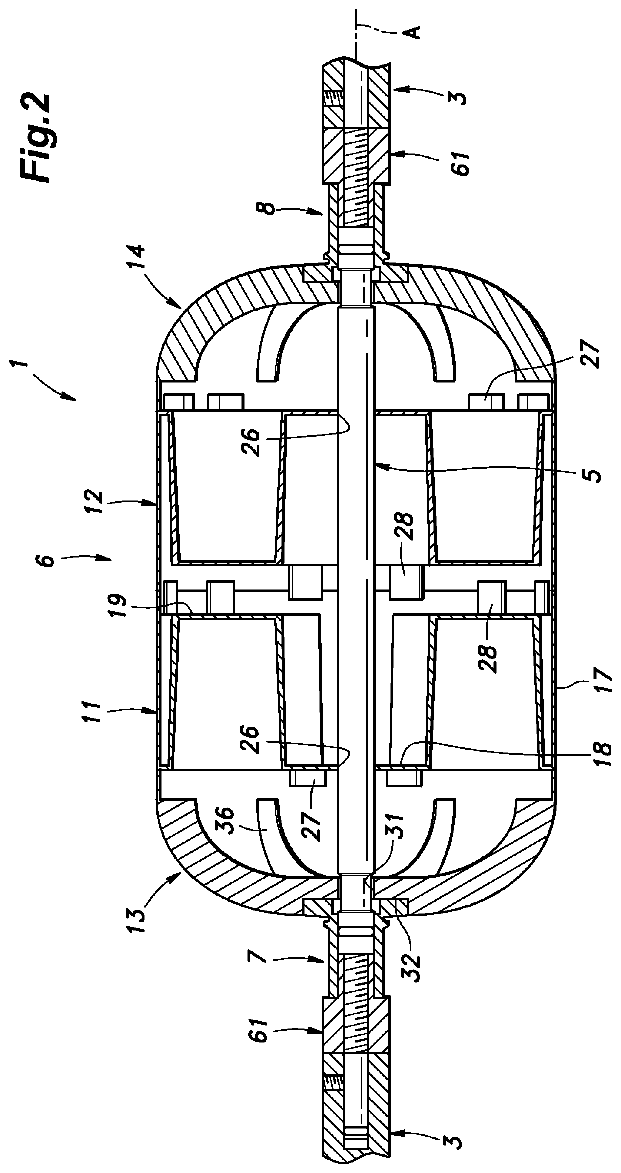
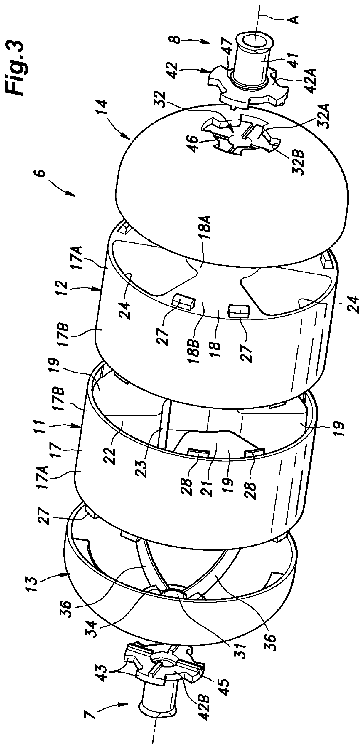
[0041]A preferred embodiment of the present invention is described in the following with reference to the appended drawings.

[0042]FIG. 1 shows a mandrel structure according to an embodiment of the present invention which is to be used for forming a fiber reinforced resin vessel 2 (see FIG. 12) by a filament winding process. In the filament winding process, the vessel 2 is formed by winding a filament of reinforcing fibers impregnated with a thermosetting resin around the mandrel structure 1. The thermosetting resin typically includes an epoxy resin, a phenol resin, an unsaturated polyester, and so on. The reinforcing fibers may be, for example, carbon fibers, glass fibers, aramid fibers, boron fibers, or the like. The reinforcing fibers preferably consist of continuous fibers, and the fibers are aligned to form a filament. The filament of reinforcing fibers impregnated with the thermosetting resin may consist of a tow prepreg.

[0043]The vessel 2 is typically configured as a pressure...


PUM

PropertyMeasurementUnit
Surface roughnessaaaaaaaaaa
Diameteraaaaaaaaaa

Abstract

A mandrel structure for use in manufacturing a fiber reinforced resin vessel by a filament winding process, includes: a shaft having a pair of axial ends configured to be supported by a drive unit; a mandrel having the shaft passed therethrough; and a pair of fittings having the shaft passed therethrough and projecting axially from respective axial ends of the mandrel. The mandrel is formed as a hollow shell made of a water-soluble material, and includes a pair of shaft holes receiving the shaft therein, and a receiving recess formed in a part of the mandrel surrounding each shaft hole and configured to engage the corresponding fitting in a rotationally fast manner.

Description

TECHNICAL FIELD[0001]The present invention relates to a mandrel structure for forming a vessel made of fiber reinforced resin by a filament winding process, and a method of manufacturing the same.BACKGROUND ART[0002]Typically, a mandrel structure is used when forming a fiber reinforced resin vessel by using the filament winding process. The mandrel structure typically includes a shaft, a mandrel supported by the shaft, and a pair of fittings supported by the shaft and placed at either axial end of the mandrel (see JPH09-323365A, for instance). The mandrel may be made of a water-soluble material. A filament made of reinforcing fibers impregnated with a thermosetting resin is wound around the mandrel, and is then heated for curing purpose. The shaft is pulled out from the mandrel, and the mandrel is dissolved with water to free the completed pressure vessel from the mandrel.[0003]When winding the reinforcing fibers impregnated with the thermosetting resin around the mandrel, the tensi...

Claims


Application Information

Patent Timeline
IPC IPC(8): B29C53/82B29C70/32B29C53/60
CPCF17C2209/2163B29C53/602B29C53/822B29C70/32B29L2031/7156F17C1/16B29C70/34B29C70/54B29C33/52B29L2031/712
Inventor TOTSUKA, MASANORINOJI, YOHEISHINNABE, YOSHIKAZUFUJIKI, KOEIMATSUZAKA, KEISUKE
Owner HONDA MOTOR CO LTD
Why Eureka
Try Eureka