
Sensor bracket

a technology of sensor brackets and brackets, which is applied in the direction of color television details, vehicle components, television systems, etc., can solve the problems of needing replacement, unstable up-down direction of the camera body on the board, etc., and achieve the effect of preventing damage to the windshield

Active Publication Date: 2017-09-28
HONDA MOTOR CO LTD
View PDF3 Cites 8 Cited by
  • Summary
  • Abstract
  • Description
  • Claims
  • Application Information

AI Technical Summary

Benefits of technology

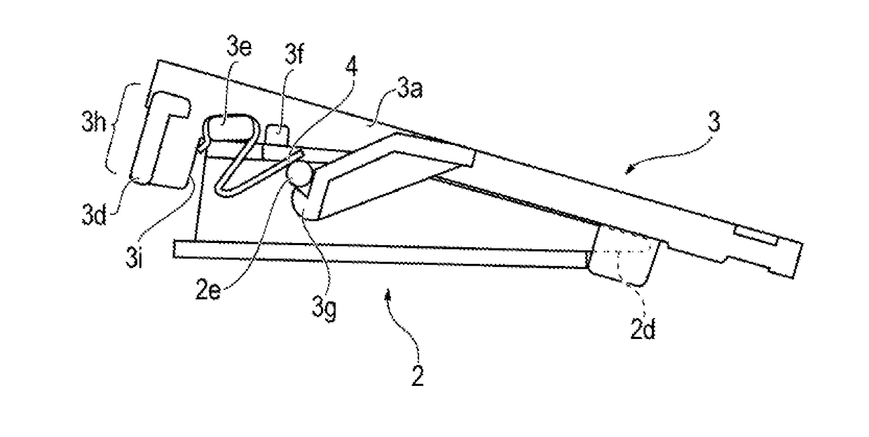
The present disclosure is about a sensor bracket that safely and easily replaces a spring member for mounting a sensor on a bracket body. The bracket includes a displacement restriction portion that prevents the tool from hitting and damaging the windshield and the like. This allows the operator to easily and safely attach the spring member while using a tool. The technical effect of this invention is to provide a safer and easier way to replace a spring member for mounting a sensor on a bracket body.

Problems solved by technology

Since the flat spring of Japanese Unexamined Patent Application Publication No. 2013-203250 biases the on-board camera body only in the front direction, the on-board camera body may be unstable in the up-down direction.
However, in Japanese Unexamined Patent Application Publication No. 2013-203250, since the flat spring is integral with the bracket, when there is a defect in the flat spring, the bracket and all need to be replaced.

Method used


Image

  • Sensor bracket
  • Sensor bracket
  • Sensor bracket

Examples


Embodiment Construction

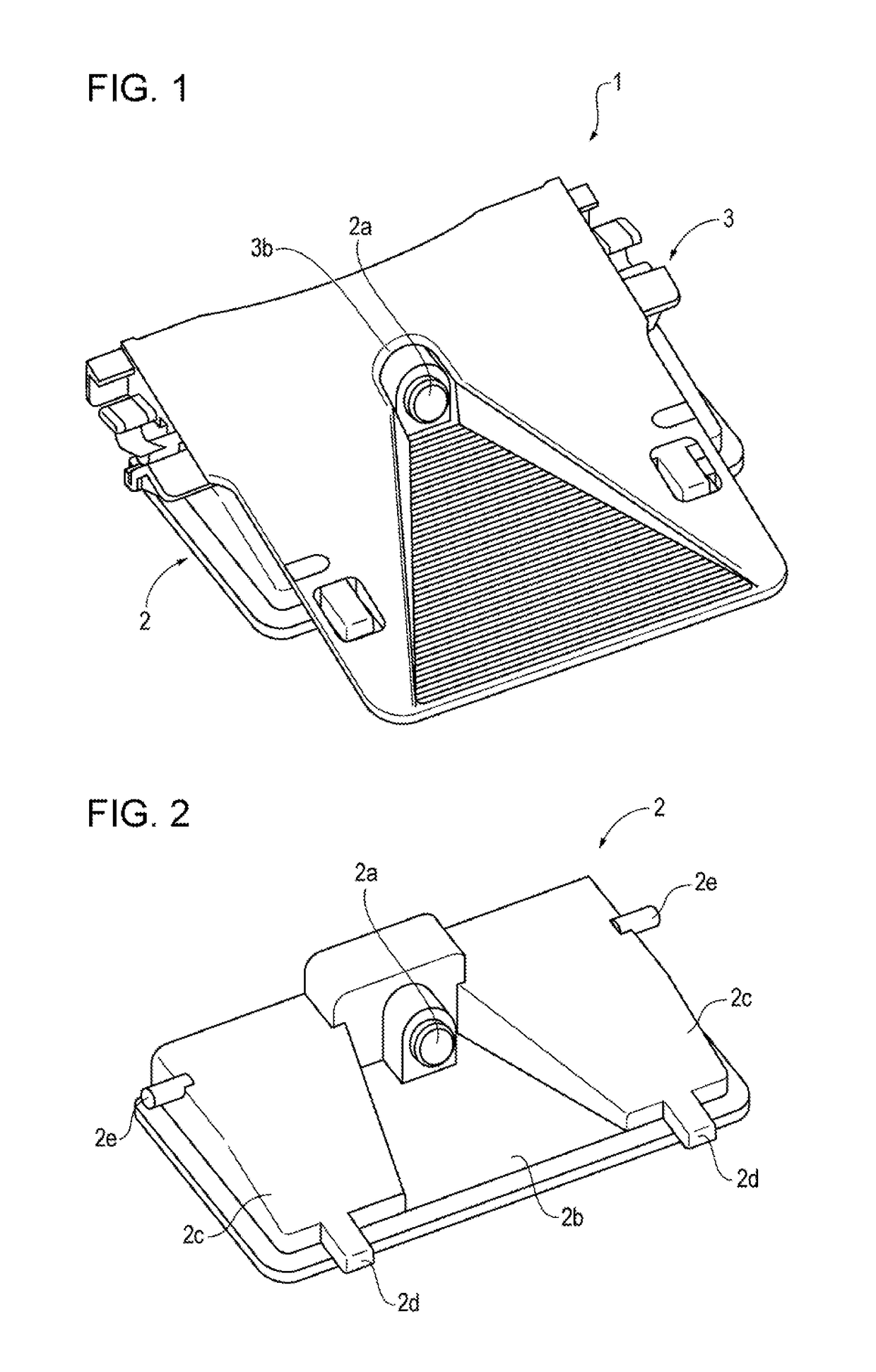
[0019]FIG. 1 illustrates a configuration in which a camera corresponding to a sensor of the present disclosure that detects the surroundings of a vehicle is mounted on a sensor bracket of the present disclosure. Hereinafter, the above configuration is referred to as a camera unit 1.

[0020]FIG. 1 is a perspective view of the camera unit 1 viewed obliquely from above. The camera unit 1 includes a camera 2 that is a sensor that performs imaging of an image in front of the vehicle, and a bracket 3 that is fixed to the windshield of the vehicle by being adhered thereon. Note that, hereinafter, description is given while the front of the vehicle is a front direction (a front side).

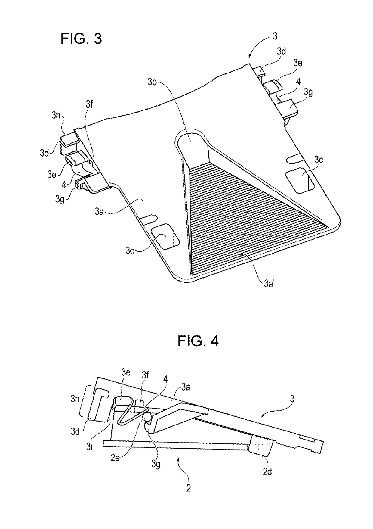
[0021]As illustrated in the drawings, the camera 2 is mounted on the bracket 3 from a lower side of the bracket 3 with an engaging mechanism described later. An opening 3b into which a lens 2a of the camera 2 is inserted is provided on an upper surface of the bracket 3. With the above, the camera 2 is capable of ...


PUM


Abstract

A sensor bracket includes a bracket on which a camera that detects a state around a vehicle is mounted, a flat spring that abuts against the camera and biasing in a direction that maintains a mounted state of the camera when the camera is mounted on the bracket, and a recess that receives a portion of a tool and restricts a displacement range of the tool when the flat spring is pressed by the tool and is mounted on a projection for the spring of the bracket.

Description

CROSS REFERENCES TO RELATED APPLICATIONS[0001]The present application claims priority under 35 U.S.C. §119 to Japanese Patent Application No. 2016-060376, filed Mar. 24, 2016, entitled “Sensor Bracket.” The contents of this application are incorporated herein by reference in their entirety.BACKGROUND1. Field[0002]The present disclosure relates to a sensor bracket used to attach an on-board camera or the like.2. Description of the Related Art[0003]Hitherto, a technique is known that accurately detects an obstacle and a pedestrian, a position of a traffic lane, whether a headlight of an oncoming vehicle is on, and the like by performing imaging of a portion in front of a vehicle with an on-board camera. In such a case, the on-board camera is mounted on a bracket that is attached to a windshield.[0004]For example, in Japanese Unexamined Patent Application Publication No. 2013-203250, while bosses of an on-board camera main body are hooked to hook-shaped portions, the on-board camera ma...

Claims


Application Information

Patent Timeline
IPC IPC(8): B60R11/04H04N5/225
CPCB60R11/04B60R2011/0026B60R2011/0084H04N5/2252B60R2011/0071B60R2011/0063H04N23/51
Inventor KASAI, KEITATOKIWA, MITSURUMATORI, TADAHIROOHMOTO, TAKAHIRO
Owner HONDA MOTOR CO LTD
Learn More