Time delay device for parachute deployment

a time delay device and parachute technology, applied in parachutes, emergency equipment, transportation and packaging, etc., can solve the problems of reducing the accuracy of cargo landing at or near the desired drop zone, and affecting the safety of personnel

Inactive Publication Date: 2017-09-28
THE SKYLIFE COMPANY
View PDF9 Cites 4 Cited by
  • Summary
  • Abstract
  • Description
  • Claims
  • Application Information

AI Technical Summary

Problems solved by technology

Deploying cargo via a HALO drop does not have the advantage of a person being able to determine when best to deploy the parachute.
1) The parachute may be damaged due to the higher speed of the aircraft.
2) The accuracy of the cargo landing at or near the desired drop zone is greatly diminished.
3) The cargo is severely damaged due to excessive shock loading on the parachute harness.

Method used


Image

  • Time delay device for parachute deployment
  • Time delay device for parachute deployment
  • Time delay device for parachute deployment

Examples


Embodiment Construction

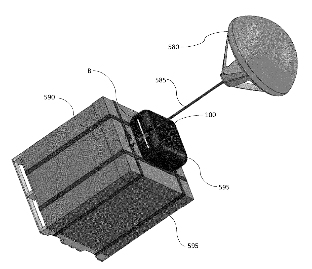
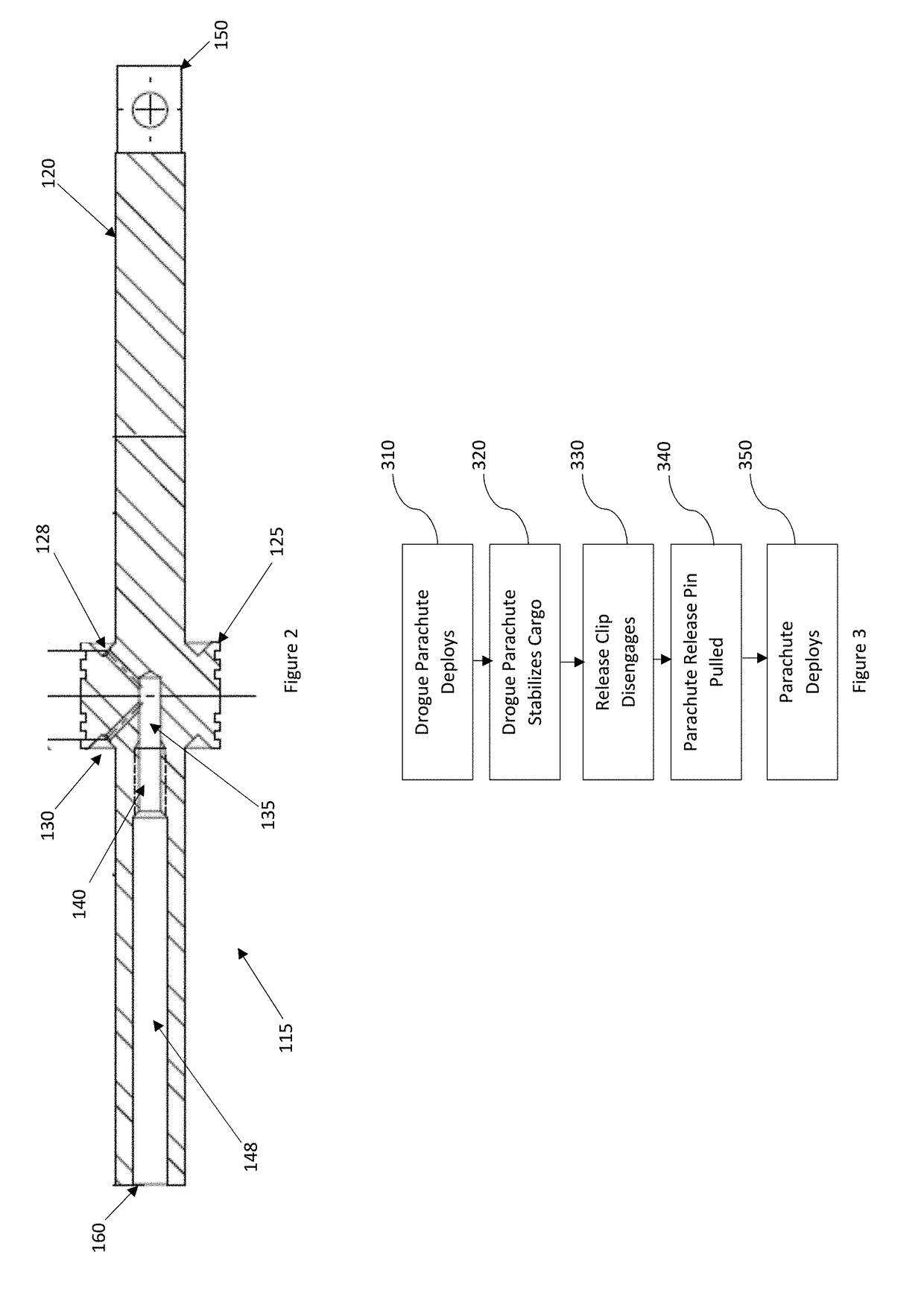
[0026]As embodied and broadly described herein, the present invention is directed to a device that utilizes a small drogue parachute attached to the cargo load and is deployed immediately as the individual cargo load exits the aircraft. The drogue chute activates the parachute deployment device, which deploys the parachute at a desired altitude.

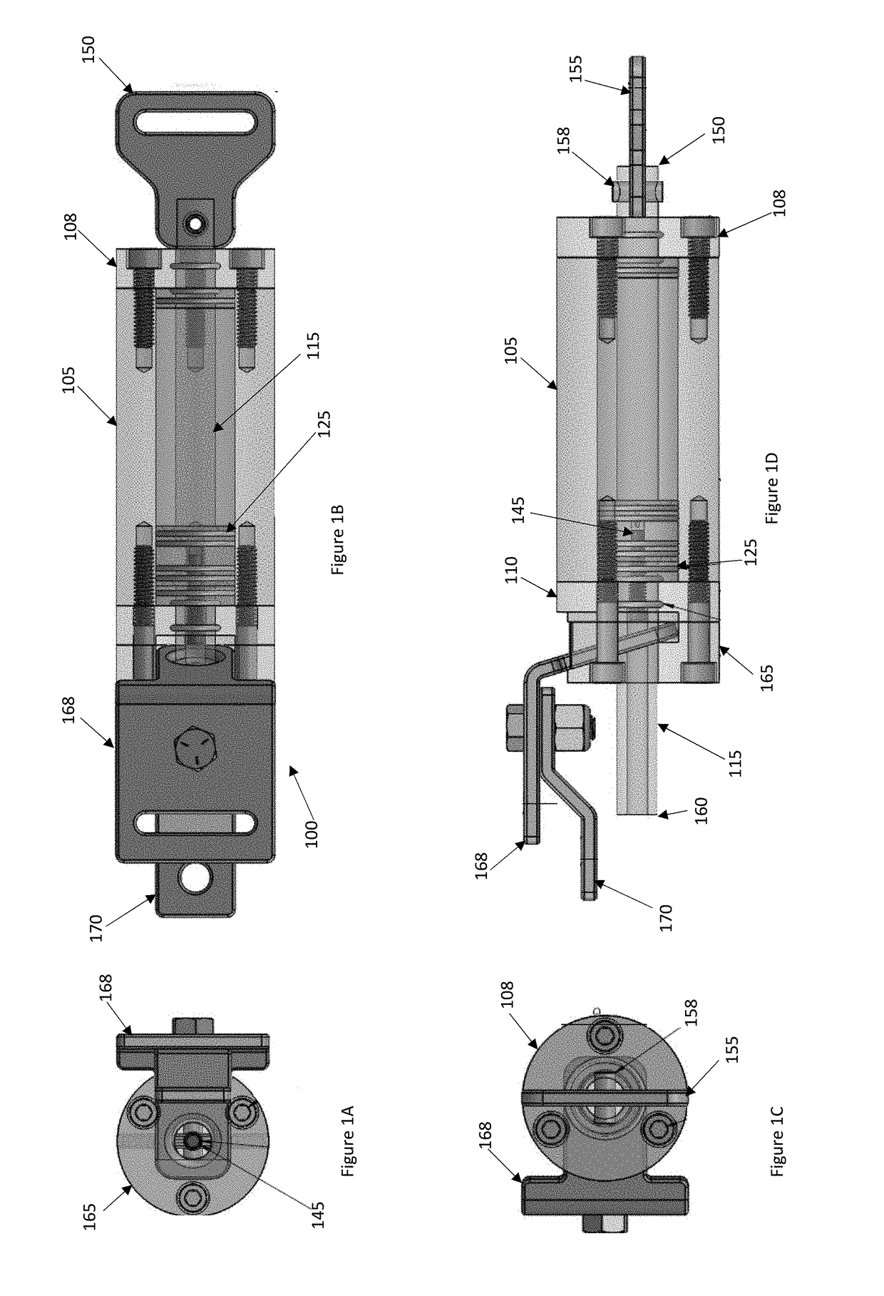
[0027]FIG. 1A depicts a top view of parachute deployment device 100. FIG. 1B depicts a side view of parachute deployment device 100. FIG. 1C depicts a bottom view of parachute deployment device 100. FIG. 1D depicts another side view of parachute deployment device 100. Preferably, parachute deployment device 100 is comprised of a tubular body 105. Although body 105 is shown as tubular, it can have another shape. Body 105 is preferably sealed at each end by endcaps 108 and 110. Endcaps 108 and 110 may be secured to body 105 by bolts (as shown), by adhesive, by welding, by friction, by threaded couplings, or another fastening device. In another ...


PUM


Abstract

Methods, devices, and systems for deploying cargo for high altitude, low opening (HALO) deployments are disclosed. The method comprises the steps of coupling a parachute deployment device to the cargo, adjusting the valve to determine rate of motion of the piston through the housing and the timing of deployment of a stored parachute, coupling the stored parachute to the parachute deployment device, coupling a drogue parachute to the parachute deployment device, and deploying the cargo from a vehicle at altitude. Upon deployment, the drogue parachute deploys and activates the parachute deployment system by pulling the piston through the housing until a release is freed from the parachute deployment system and the parachute is deployed. The parachute deployment device comprises a housing containing a fluid, a piston adapted to move within the fluid contained in the housing, and an adjustable valve coupled to the piston accessible from outside the housing.

Description

REFERENCE TO RELATED APPLICATIONS[0001]This application claims priority to U.S. Provisional Application Ser. Nos. 62 / 313,286, filed Mar. 25, 2016, and 62 / 382,451, filed Sep. 1, 2016, both entitled “Time Delay Device for Parachute Deployment,” both of which are hereby specifically and entirely incorporated by reference.BACKGROUND1. Field of the Invention[0002]This invention is directed to devices and methods for automatically opening a parachute. Specifically, the invention is also directed to devices and methods for delayed opening of a parachute during high altitude low opening deployment.2. Description of the Background[0003]High altitude low opening (“HALO”) parachuting is a method of deploying personnel, equipment, and supplies to the ground from aircraft flying at high altitudes. During a HALO drop, the person or package free-falls though the air for a period of time prior to the parachute opening. The parachute may be manually opened by a parachutist or automatically opened up...

Claims


Application Information

Patent Timeline
Patent Type & Authority Applications(United States)
IPC IPC(8): B64D17/58
CPCB64D17/58
Inventor POTTER, JEFFERY J.POTTER, TERRY C.KUJAWA, ANTHONY J.
Owner THE SKYLIFE COMPANY
Why Eureka
Try Eureka