Liquid jetting apparatus

a technology of liquid jetting apparatus and nozzle chips, which is applied in the direction of printing and inking apparatus, etc., can solve the problems of difficult to make the limit of the difficulty of reducing the distance between the two nozzle chips belonging to the two adjacent head units, etc., to suppress the uneven density, the width of overlapping, and the uneven density

Active Publication Date: 2017-10-05
BROTHER KOGYO KK
View PDF6 Cites 10 Cited by
  • Summary
  • Abstract
  • Description
  • Claims
  • Application Information

AI Technical Summary

Benefits of technology

[0005]In the ink-jet head having the above-described configuration, a portion or location between two adjacent nozzle chips, included in the plurality of nozzle chips, in which an end portion of one of the two adjacent nozzle chips and an end portion of the other of the two adjacent nozzle chips are adjacent in the width direction of the recording sheet, tends to have any deviation in the landing positions of liquid droplets jetted respectively from the two adjacent nozzle chips, and / or any unevenness in the concentration (density) due to any difference in the jetting characteristic between the two adjacent nozzle chips, which easily occur in the portion or location between the two adjacent nozzle chips. In order to make the unevenness in the density to be less conspicuous, it is preferred that the two nozzle chips are arranged such that nozzle arrangement areas, in each of which the plurality of nozzles are arranged, of the respective two chips are partially overlapped with each other. Further, as the width of overlapping in which the nozzle arrangement areas are allowed to overlap partially with each other is made to be greater, more effect can be achieved in suppressing the unevenness in the density.

Problems solved by technology

However, in view of assembling the respective head units, it is not possible to arrange two adjacent head units side by side without any gap therebetween, and there is also a limit in decreasing the distance between two nozzle chips belonging to the two adjacent head units, respectively.
Accordingly, it is difficult to make the width of overlapping in which the nozzle chips are allowed to overlap partially with each other to be great between the two adjacent head units.

Method used


Image

  • Liquid jetting apparatus
  • Liquid jetting apparatus
  • Liquid jetting apparatus

Examples


modification 1

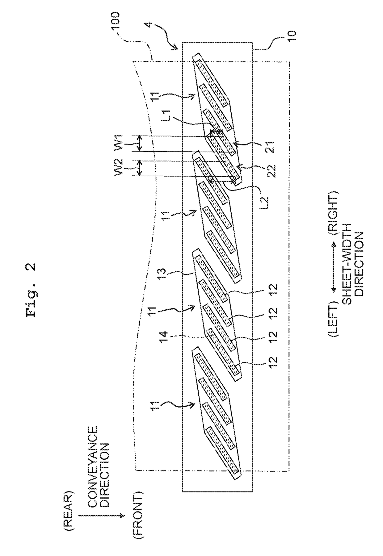
[0072]In the above-described embodiment, the overlapping width W2 of the second overlapping portion 22 is made to be same as the overlapping width W1 of the first overlapping portion 21. It is allowable, however, that the overlapping width W2 may be greater or smaller than the overlapping width W1. Further, in the above-described embodiment, although the overlapping widths W2 are same in all the three second overlapping portions 11 regarding the four head units 4, it is allowable that the overlapping width W2 of the three overlapping portions 22 may be different from one another regarding the four head units 4. In such a case, in two head units 11 which are adjacent in the left / right direction, the overlapping widths W2 of the second overlapping portions 22 may be determined, respectively, depending on the jetting characteristic of a rightmost nozzle chip 12 included in a left-side head unit 11 among the two adjacent head units 11 and the jetting characteristic of a leftmost nozzle ...

modification 2

[0073]In the above-described embodiment, there is provided such an aspect that the inclination (angle θ1) of the nozzle chip 12 relative to the left / right direction is made to be relatively small, in view of increasing the overlapping width W1 of the first overlapping portion 21 between the two nozzle chips 12. With respect to this configuration, it is also possible to increase the inclination of the nozzle chip 12 so as to decrease the arrangement interval (spacing distance) between the nozzles 14 in the left / right direction, for the purpose of realizing an ink-jet head capable of performing high-resolution printing.

[0074]From the foregoing viewpoint, as in an ink-jet head 4A of FIG. 6 and a head unit 11A of FIG. 7, the inclination angle θ1 of each of the nozzle chips 12 may be made great. Specifically, the inclination angle θ1 may be in a range of 45 degrees≦θ114 in the chip longitudinal direction is “P”, then the arrangement interval between the nozzles 14 in the left / right direc...

modification 3

[0077]The arrangement of the plurality of nozzle chips 12 within one head unit is not limited to the configuration of the above-described embodiment. In order to increase the overlapping width of the nozzle chips 12 between the two head units, it is sufficient that at least the right-end nozzle chip 12 and the left-end nozzle chip 12 are arranged such that the positions in the chip shifting direction thereof are shifted from each other, and that the remaining configuration other than this can be appropriately changed.

[0078]For example, as in a head unit 11C of FIG. 9, it is allowable that the shifting direction is changed halfway among the four nozzle chips 12, rather than shifting all of the four nozzle chips 12 in order (one by one) in a predetermined one direction. Alternatively, as in a head unit 11D of FIG. 10A, is it allowable to provide such a configuration wherein central two nozzle chips 12 which are located at a central portion among the four nozzle chips 12 are arranged s...


PUM


Abstract

A liquid jetting apparatus jetting a liquid onto a recording medium conveyed in a first direction includes head units arranged in a second direction orthogonal to the first direction. One head unit includes nozzle chips; one nozzle chip has a nozzle arrangement area wherein nozzles are aligned in a third direction crossing the first and second directions. The nozzle chip is arranged to be shifted relative to another nozzle chip in a direction crossing the first and second directions and different from the third direction. The head unit has a first overlapping portion wherein nozzle arrangement areas of first and second nozzle chips included in the nozzle chips partially overlap with each other in the first direction. The liquid jetting apparatus has a second overlapping portion wherein nozzle arrangement areas of third and fourth nozzle chips included in the head units partially overlap with each other in the first direction.

Description

CROSS REFERENCE TO RELATED APPLICATION[0001]The present application claims priority from Japanese Patent Application No. 2016-071147 filed on Mar. 31, 2016 the disclosure of which is incorporated herein by reference in its entirety.BACKGROUNDField of the Invention[0002]The present invention relates to a liquid jetting apparatus.Description of the Related Art[0003]Conventionally, there is known an ink-jet head of a line type, as a liquid jetting apparatus. This head is provided with a plurality of head units (ink-jet recording heads) arranged side by side in the width direction of a recording sheet which is orthogonal to a conveyance direction of the recording sheet.[0004]Each of the head units (hereinafter referred to as “one head unit”, as appropriate) has a plurality of nozzle chips (head bodies) which are arranged side by side in the width direction of the recording sheet, and a holder configured to hold the plurality of nozzle chips. The respective nozzle chips extend in an obli...

Claims


Application Information

Patent Timeline
Patent Type & Authority Applications(United States)
IPC IPC(8): B41J2/155B41J2/045
CPCB41J2/155B41J2/04586B41J2/04505B41J2/145B41J2/2146B41J2202/19B41J2202/20
Inventor MIZUNO, TAISUKEHAYASHI, HIDEKISUGIURA, KEITA
Owner BROTHER KOGYO KK
Why Eureka
Try Eureka