Positioning Arrangement For Fitting An Interchangeable Milling Assembly Of A Road-Building Machine

a technology of interchangeable milling and road-building machines, which is applied in the direction of roads, roads maintainence, roadways, etc., can solve the problems of loss of machine maneuverability, large working width of milling assemblies, and inability to allow the milling drum to be pivoted, so as to simplify the use of road milling machines

Active Publication Date: 2017-10-05
WIRTGEN GMBH
View PDF0 Cites 3 Cited by
  • Summary
  • Abstract
  • Description
  • Claims
  • Application Information

AI Technical Summary

Benefits of technology

[0005]The object underlying the invention is to simplify the use on road milling machines of milling assemblies whose working width is greater than the permitted width for transport of the road milling machine.
[0006]The fitting of an interchangeable milling assembly of quite a large working width below the vertically adjustable chassis of a road milling machine is made easier in accordance with the invention by a positioning arrangement which takes the form of a vehicle carried on a plurality of wheels which has a unit for receiving the milling assembly, with at least one wheel being steerable. The positioning arrangement has a handling chassis which can be lengthened in the longitudinal direction and to which the wheels are fixed, to be adjustable vertically relative to the handling chassis, in such a way that the handling chassis can be moved from a position in which it is lowered to a position in which it is raised.

Problems solved by technology

This possible procedure is only rarely adopted in practice because the fitting and removal of the milling assembly is time-consuming and labour-intensive due to the large number of steps which the fitting involves and the great weight of the milling assembly.
Milling assemblies of a large working width are therefore not very widely accepted in practice.
However, modern-day road milling machines, stabilisers and recyclers have a mechanical drive which does not allow the milling drum to be pivoted.
Also, the above solution calls for a considerably longer wheel base, which means a loss of maneuverability for the machine.

Method used


Image

  • Positioning Arrangement For Fitting An Interchangeable Milling Assembly Of A Road-Building Machine
  • Positioning Arrangement For Fitting An Interchangeable Milling Assembly Of A Road-Building Machine
  • Positioning Arrangement For Fitting An Interchangeable Milling Assembly Of A Road-Building Machine

Examples


Embodiment Construction

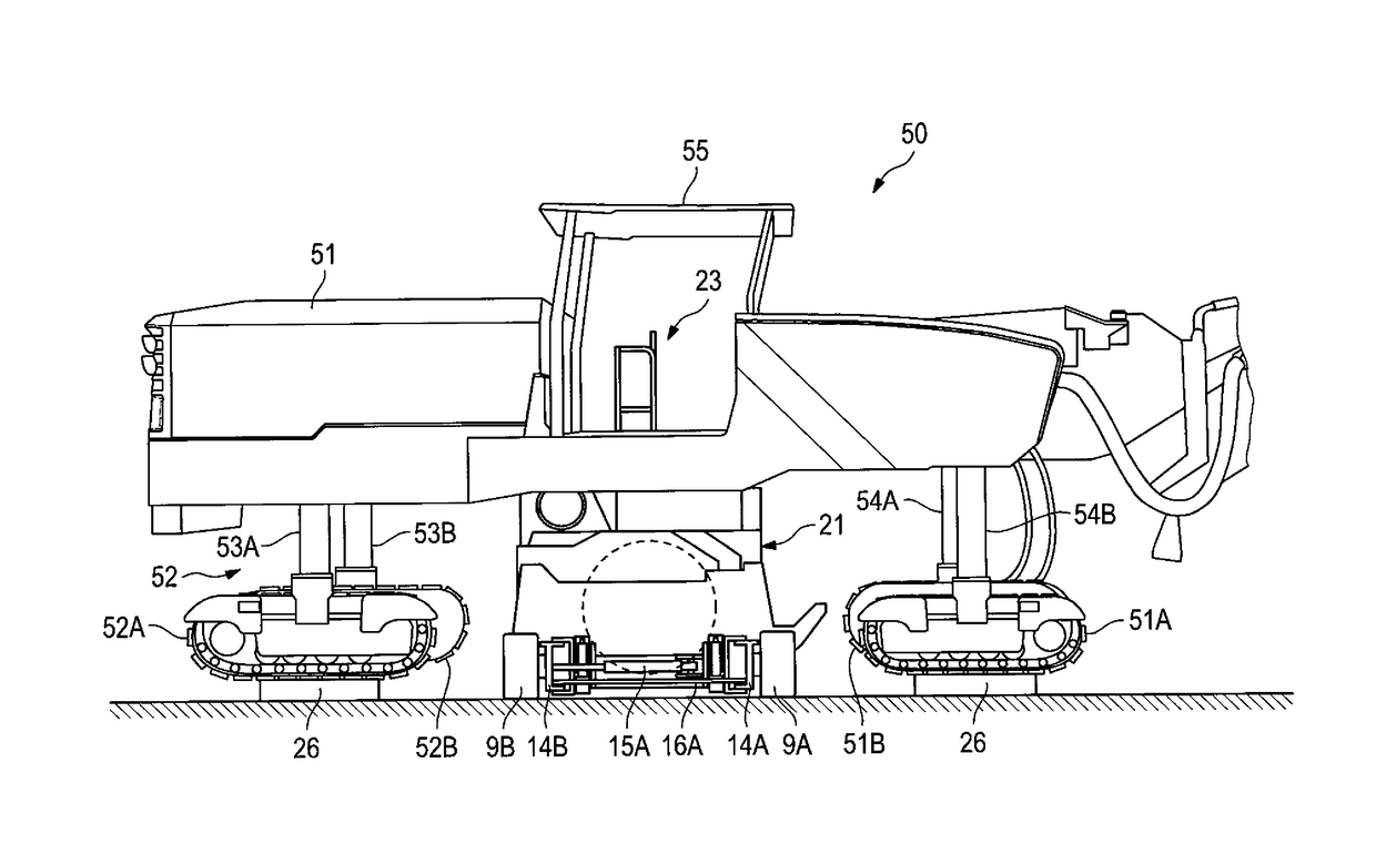
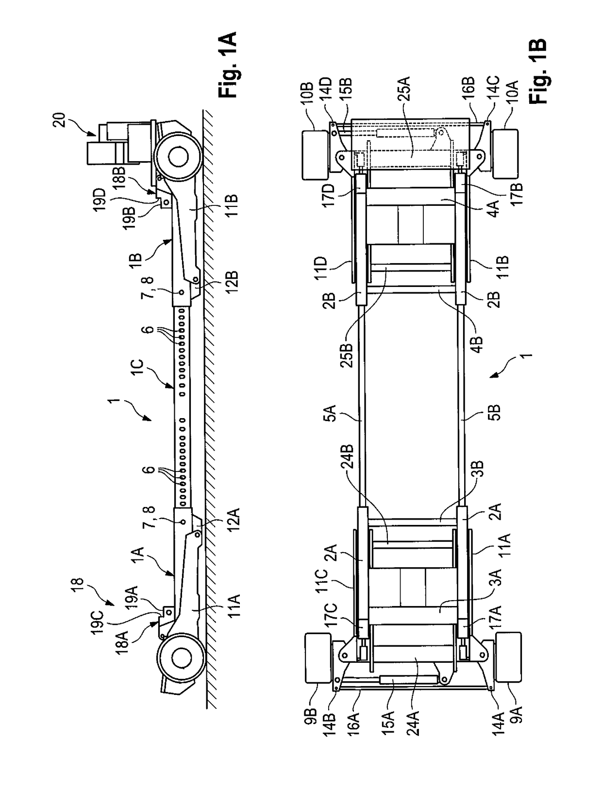
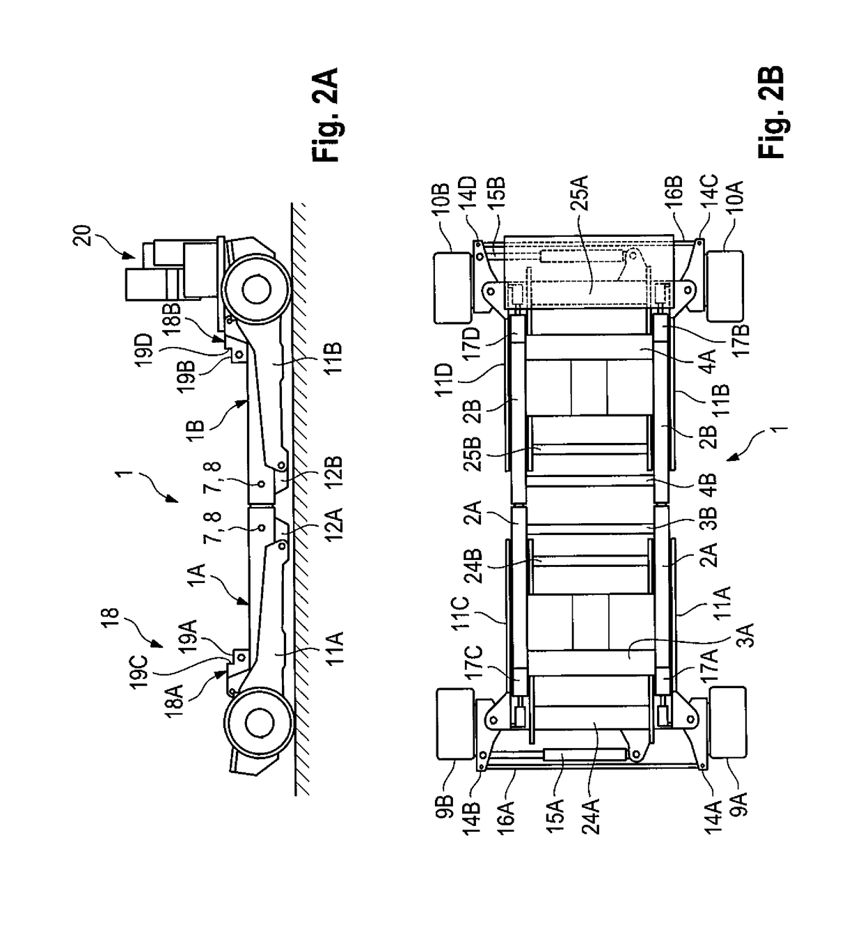
[0038]FIGS. 1A and 1B to 4A and 4B are views from the side and plan views of the positioning arrangement in its different operating positions. The positioning arrangement takes the form of a vehicle carried on a plurality of wheels which has a receiving unit for milling assemblies of different working widths which are not shown in FIGS. 1A, 1B to 4A, 4B.

[0039]The positioning arrangement is a self-propelled arrangement. It has an elongated handling chassis 1 which can be lengthened in the longitudinal direction. In FIGS. 1A and 1B the handling chassis 1 is shown in the position where it is extended to its maximum length whereas FIGS. 2A and 2B show the handling chassis in the position where it is closed up to its minimum length. The handling chassis can however also be extended to set lengths which are between these two positions. The length of the handling chassis can thus be set exactly to the working width of the milling assembly which is to be fitted.

[0040]Although the positionin...


PUM

PropertyMeasurementUnit
heightaaaaaaaaaa
lengthaaaaaaaaaa
widthaaaaaaaaaa

Abstract

The invention relates to a positioning arrangement for fitting an interchangeable milling assembly of a preset working width below the vertically adjustable chassis of a road milling machine, which chassis is carried on track-laying units. A vehicle carried on a plurality of wheels has a unit for receiving the milling assembly. The positioning arrangement has a handling chassis which can be lengthened in the longitudinal direction and to which the wheels are fixed. In a lowered position, the positioning arrangement, with the milling assembly resting on it, can be driven below the chassis of the road milling machine. In a raised position, the milling assembly can be fitted to the road milling machine.

Description

BACKGROUND OF THE INVENTION1. Field of the Invention[0001]The invention relates to a positioning arrangement for fitting an interchangeable milling assembly of a preset working width below the vertically adjustable chassis of a road building machine such as a road milling machine, stabiliser or recycler, which chassis is carried on wheels or track-laying units.2. Description of the Prior Art[0002]Known road milling machines are used for renovating asphalt or concrete carriageways. To mill away the surface of the carriageway, known road milling machines have a milling assembly which has a milling drum fitted with milling chisels. The milling assembly of known road milling machines is arranged below the chassis of the machine between the front and rear track-laying units which carry the chassis of the machine.[0003]Road milling machines having milling assemblies of different working widths are known. If large milling machines are fitted with milling assemblies whose working width exce...

Claims


Application Information

Patent Timeline
Patent Type & Authority Applications(United States)
IPC IPC(8): E01C23/088
CPCE01C23/088Y10T29/49826E01C23/08
Inventor BUSLEY, PETERBARIMANI, CYRUSSALZ, ANDREAS
Owner WIRTGEN GMBH
Why Eureka
Try Eureka