Inter-network interference coordination method

a technology of inter-network interference and coordination method, which is applied in the direction of digital transmission, electrical equipment, transmission path sub-channel allocation, etc., can solve the problems of difficult sharing of detailed information about network deployment between the different operators, the power of the base station, and the loss of wireless signals through the wall, so as to achieve effective interference coordination, improve network performance, and improve the effect of interference coordination

Inactive Publication Date: 2017-10-05
SHANGHAI RES CENT FOR WIRELESS COMM
View PDF13 Cites 7 Cited by
  • Summary
  • Abstract
  • Description
  • Claims
  • Application Information

AI Technical Summary

Benefits of technology

[0021]Compared with the prior art, the invention effectively solves interference coordination between networks with the same priority; when strong inter-network interference exceeds a threshold, intra-network coordination is first conducted, and inter-network coordination is then conducted; while the networks with the same priority can fairly and reasonably use a shared frequency band, the efficiency of interference coordination is increased, and network performance is effectively improved.

Problems solved by technology

Compared with macro base stations, the transmission power of the base stations of these small cells is much lower, and moreover, in some indoor deployment scenarios, wireless signals will have great through-wall loss when penetrating a building.
However, in a spectrum sharing scenario between different operators, on one hand, because of business competition and network security, detailed information about network deployment is hard to be shared between the different operators; and on the other hand, the existing neighboring cell measurement mechanism in the same operator includes too much sensitive information, and the sharing of these sensitive information may not be supported by the operators.
These two limitations bring a challenge to interference coordination between different operators.
However, previous works related to interference evaluation and coordination in co-primary spectrum sharing scenarios have not been seen yet.

Method used


Image

  • Inter-network interference coordination method
  • Inter-network interference coordination method
  • Inter-network interference coordination method

Examples


first embodiment

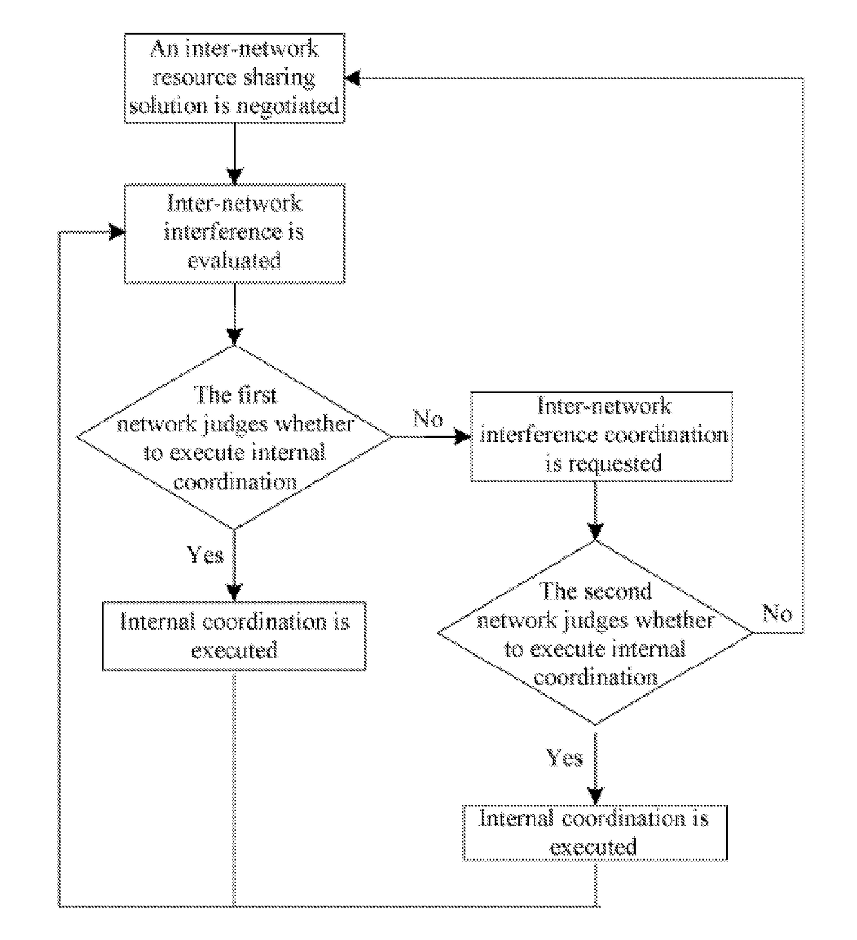
[0036]As shown in FIG. 1, the overall solution of the first embodiment includes the following steps:

[0037]negotiating an inter-network resource sharing solution;

[0038]evaluating inter-network interference;

[0039]the first network judging step that the first network judges whether to execute internal coordination, if it is judged that internal coordination can be executed, then the first network executes internal coordination, and then turn to the step of “evaluating inter-network interference”; if it is judged that internal coordination cannot be executed, then inter-network interference coordination is requested, and the next step is executed; and

[0040]the second network judging step that the second network judges whether to execute internal coordination, if internal coordination can be executed, then the second network executes internal coordination, and then turn to the step of “evaluating inter-network interference”; if internal coordination cannot be executed, then turn to the s...

second embodiment

[0123]In order to briefly introduce the second embodiment of the invention, only the differences of the second embodiment from the first embodiment are described.

[0124]FIG. 6 shows network-specific inter-network interference of each carrier in a shared spectrum pool of the second embodiment. Different from FIG. 4 in the first embodiment, the network-specific inter-network interference value in the second embodiment, which is is quantified and divided into high interference, medium interference and low interference, while the network-specific inter-network interference value in the first embodiment is non-quantified. The signaling format of the network-specific inter-network interference value in the second embodiment is as follows. Different from the “Signaling Content” of the first embodiment, the “Signaling Content” of the second embodiment is interference level description (quantified values).

SignalingSignalingSpecificNameRangeContentDescriptionnetwork-1-N (N is ainterferencecorr...

third embodiment

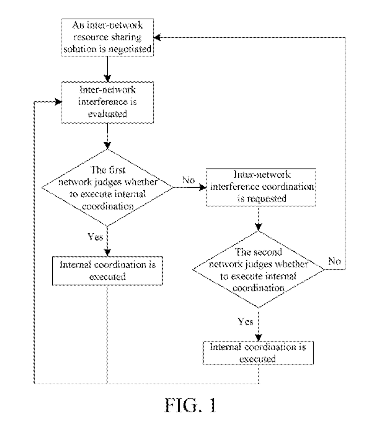
[0137]The flows in FIG. 1, FIG. 2 and FIG. 3 in the invention are event-triggered examples, and the flows in FIG. 7 and FIG. 8 are periodically triggered examples. Referring to FIG. 7 and FIG. 8, a case of periodically communicating network-specific inter-network interference information which is provided by the third embodiment is introduced below.

[0138]Under the condition that network-specific inter-network interference indication communication between operators is the periodical triggering mode, in every T time, network-specific inter-network interference indication which is generated in the previous period of measurement is communicated between the two networks.

[0139]The first network periodically sends network-specific inter-network interference indication to all the networks spectrum-sharing with the first network, including the second network. Each network spectrum-sharing with the first network judges alone which cells deployed in the network cause interference on the first ...


PUM


Abstract

Disclosed is a network interference coordination method in a co-primary spectrum sharing scenario. The method comprises the following steps: a first network and a second network negotiate an inter-network shared band, the shared band being in a shared spectrum pool; the first network evaluates inter-network interference; the first network determines whether to perform internal coordination, if internal coordination is performed, the first network performs internal coordination; if internal coordination is not performed, request the second network to perform inter-network interference coordination; the second network determines whether to perform internal coordination, if internal coordination is performed, the second network performs internal coordination; and if internal coordination is not performed, go back to the step of negotiating, by a first network and a second network, an inter-network shared band. The present invention can fairly and properly implement inter-network interference coordination in the co-primary spectrum sharing scenario.

Description

BACKGROUNDTechnical Field[0001]The invention relates to an inter-network interference coordination method, and in particular to an interference coordination method used between networks with the same priority, which belongs to the technical field of wireless communications.Related Art[0002]Co-primary Spectrum Sharing is a novel spectrum access mode, which can realize dynamic, flexible co-primary spectrum sharing between different operators. It requires two or more wireless frequency band license holders to reach consensus by negotiating on how to use respective partial authorized frequency bands together. The whole spectrum sharing mode is controlled by the national frequency band management agency. Therefore people are assuming a novel mode: the frequency band management agency does not allocate a section of spectrum resource to a certain operator in an exclusive way anymore but to a number of potential operators (users) at the same time. These potential operators (users) need to f...

Claims


Application Information

Patent Timeline
Patent Type & Authority Applications(United States)
IPC IPC(8): H04W72/08H04L5/00H04W16/14
CPCH04W72/082H04L5/0032H04W16/14H04W16/10H04W72/541
Inventor ZHU, YUANPINGWANG, JIANGYU, QIAOLINGTENG, YONGHORNEMAN, KARI
Owner SHANGHAI RES CENT FOR WIRELESS COMM
Why Eureka
Try Eureka