Table saw having a blade height adjustment mechanism

a technology of height adjustment mechanism and table saw, which is applied in the field of table saws, can solve the problems of unfavorable patent use, seat, threaded rod, seat dislocation,

a technology of height adjustment mechanism and table saw, which is applied in the field of table saws, can solve the problems of unfavorable patent use, seat, threaded rod, seat dislocation,

US20170297122A1Active Publication Date: 2017-10-19CHANG CHIN CHIN

Image

  • Table saw having a blade height adjustment mechanism
  • Table saw having a blade height adjustment mechanism
  • Table saw having a blade height adjustment mechanism

Examples


Embodiment Construction

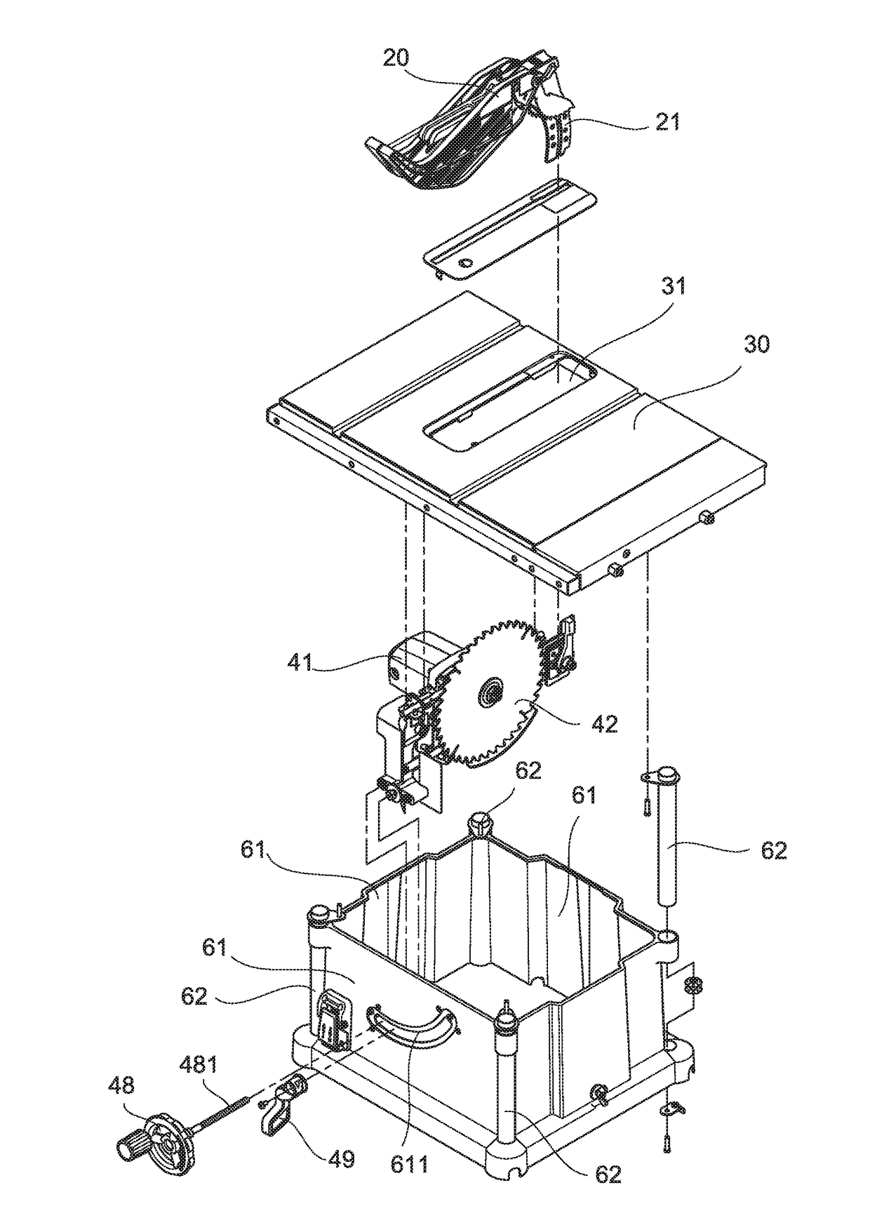
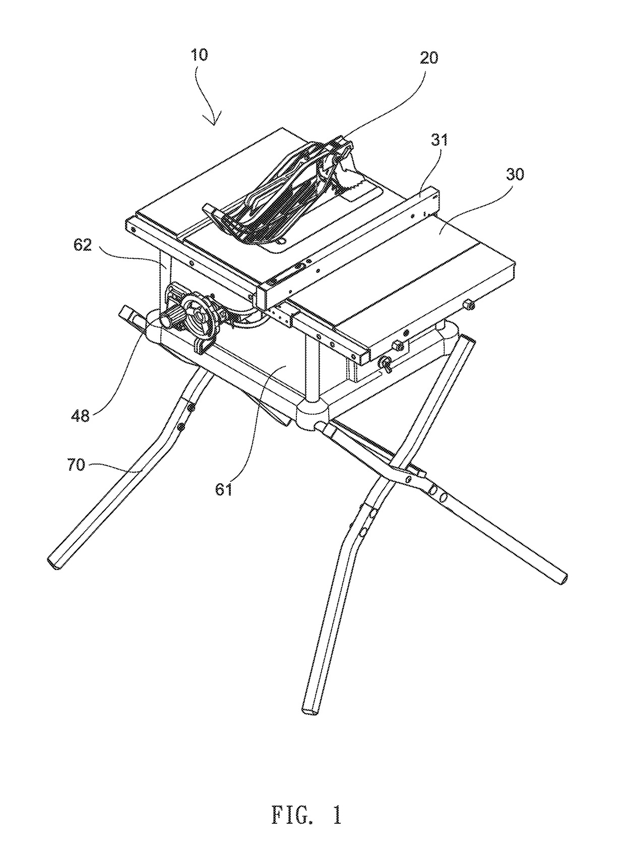
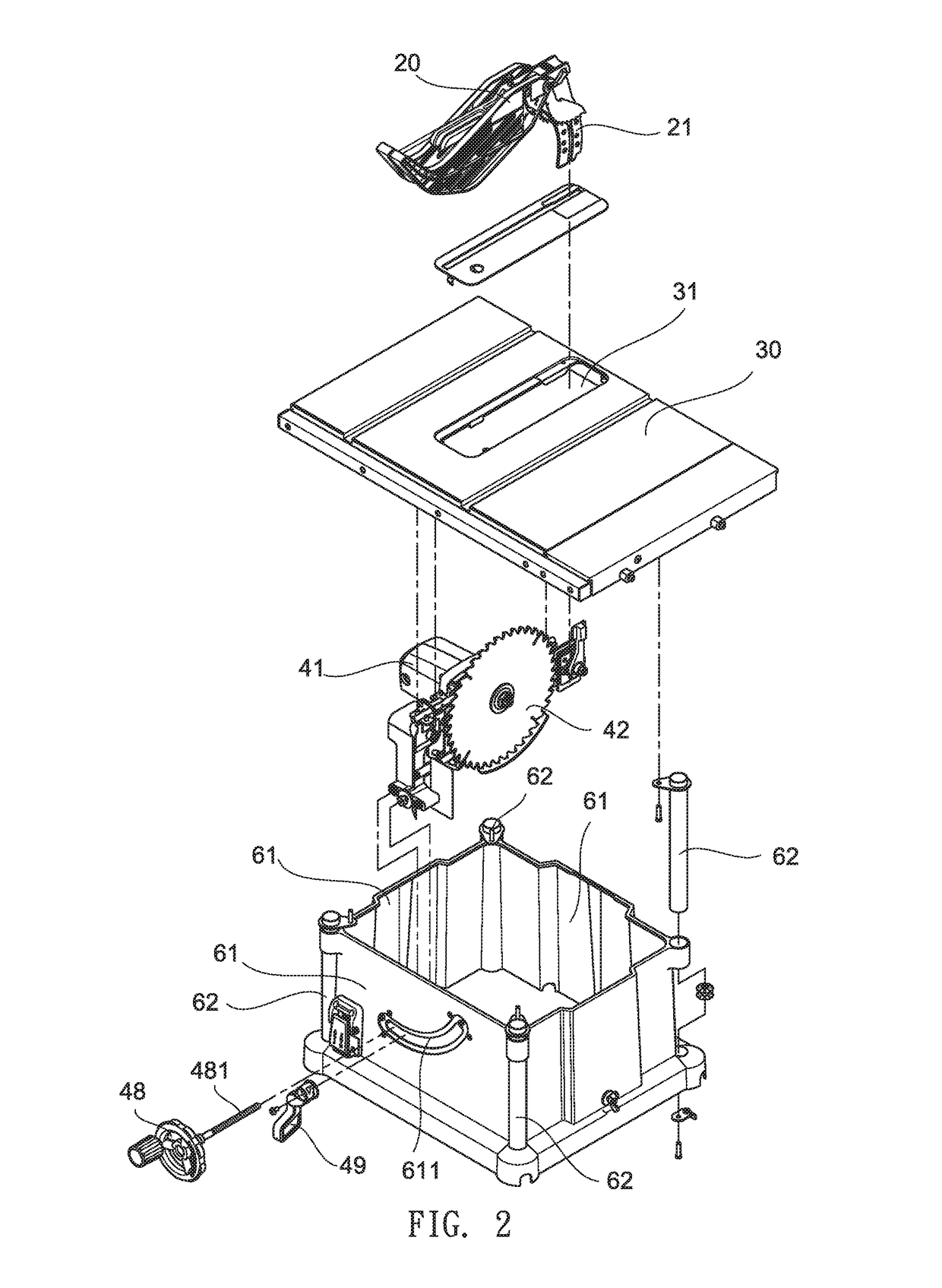
[0022]Referring to FIGS. 1 to 11a, a table saw 10 in accordance with the invention is shown and comprises a hollow, parallelepiped base 60 including four panels 61, an upward curved slot 611 in the front one of the panels 61, and four corner posts 62, a folding leg assembly 70 threadedly secured to the corner posts 62 by means of a plurality of fasteners to fasten the base 60 and the leg assembly 70 together and configured to support the base 60, an upper cutting surface 30 threadedly mounted on the base 60 by means of a plurality of fasteners, a rip fence 31 slidably mounted on the cutting surface 30, a saw guard 20 mounted around an opening 31 of the cutting surface 30 besides the rip fence 31, the saw guard 20 including a curved slot 201 with an upper portion of a downward extending bifurcated member 21 moveably secured thereto so that the saw guard 20 may move back and forth along the slot 201 when the bifurcated member 21 is locked or a portion of the bifurcated member 21 joine...


PUM

PropertyMeasurementUnit
Angleaaaaaaaaaa
Timeaaaaaaaaaa
Heightaaaaaaaaaa

Abstract

A table saw includes a height adjustment wheel including a threaded shaft; a blade suspension mechanism secured to a lock crank; a rod secured to both the blade suspension mechanism and a bottom of the cutting surface; an electric motor including a driving shaft and a link extending forward to secure to the blade suspension mechanism; a circular saw blade operatively connected to the driving shaft; first and second mounting plates each secured to the link and including a slanted slot element; and an interconnection including two end holes moveably disposed in the slot elements of the first and second mounting plates respectively, and an intermediate threaded hole secured to the threaded shaft. A rotation of the height adjustment wheel moves the saw blade up or down.

Description

BACKGROUND OF THE INVENTION1. Field of the Invention[0001]The invention relates to table saws and more particularly to a table saw having a blade height adjustment mechanism with improved characteristics.2. Description of Related Art[0002]Table saw is a woodworking tool consisting of a circular saw blade, mounted on an arbor which is driven by an electric motor. The blade protrudes through the surface of a table, which provides support for the material (e.g., wood) being cut.[0003]U.S. Pat. No. 6,820,527 entitled “table saw having a blade suspension structure” discloses a table saw having a blade suspension structure, comprising a work table formed with a cutting slot for passage of a circular blade; a suspension rod secured on the bottom of the work table and having a bottom face formed with a recessed flattened face; a motor gear box rotatably mounted on the suspension rod and located under the suspension rod, the motor gear box having a top face formed with a recess facing the fl...

Claims


Application Information

Patent Timeline
19 Oct 2017
Publication
US20170297122A1
IPC
B23D45/06
CPC
B23D45/068; B27G19/08; Y10T83/7705; Y10T83/7726; Y10T83/773
Inventors
CHANG, CHIN-CHIN