Bipod with compressively popping up inner leg assemblies

Inactive Publication Date: 2017-10-19
CHEN XIAOMING
View PDF0 Cites 5 Cited by
  • Summary
  • Abstract
  • Description
  • Claims
  • Application Information

AI Technical Summary

Benefits of technology

[0027]The present invention can be used for supporting rifles for competition in precision shooting, such as shooting competitions and hunting. With respect to the prior art, the present invention is advantageous in that: the two switch locks can be operated by two hands respectively at the same time, and when the switch lock is pressed, the inner leg pops up instantly from a rear-end of the out pipe with the interposition of the elastic force of the compression spring, to realize quick adjustment of a rifle, which can conveniently adapt t

Problems solved by technology

Bipods with the same type bipod seat now available in the market compressively pop up by an external spring on a front-end of legs, which has the following drawbacks: the spring is installed exposed to a front end surface of a pipe, whose compression causes damage to the end surface of the pipe and affects appearance and stability of popping up of legs.
Additionally, as the same type structure of inner legs and external pipes now available in the market is not pro

Method used


Image

  • Bipod with compressively popping up inner leg assemblies
  • Bipod with compressively popping up inner leg assemblies
  • Bipod with compressively popping up inner leg assemblies

Examples


Example

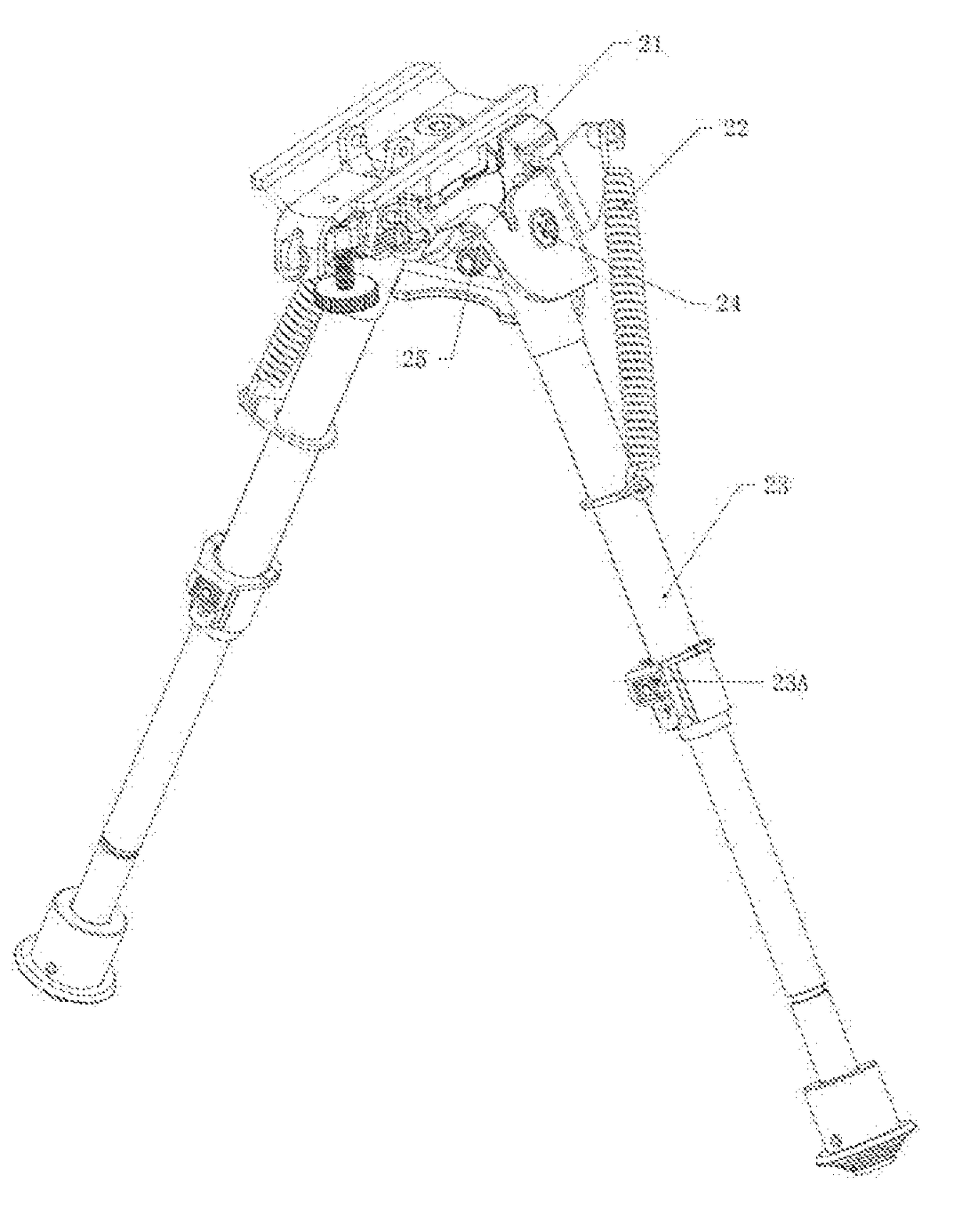
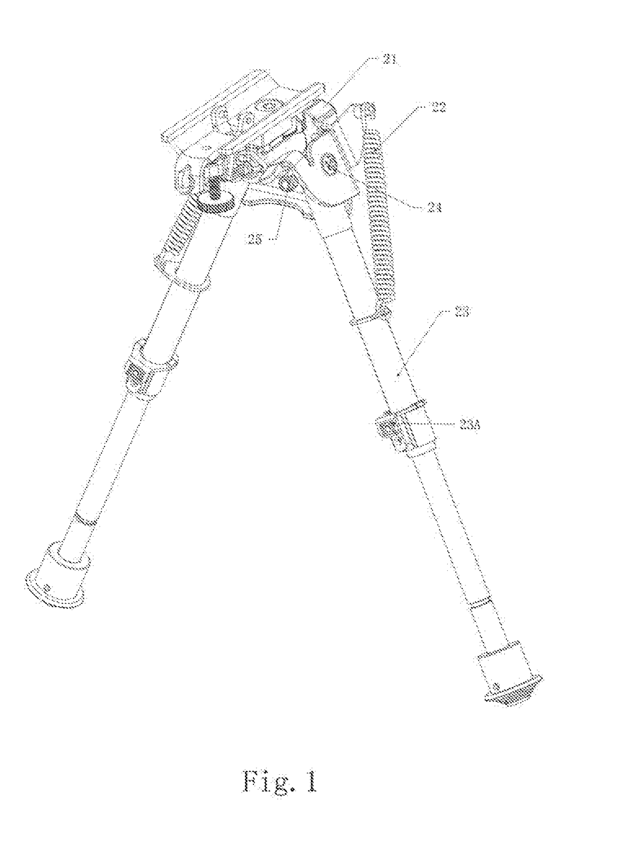
[0040]FIG. 1 is a perspective view of a first embodiment of a bipod according to the present invention, which comprises a bracket assembly 21; at least two pop up inner leg assemblies 23 pivotally connected to the bottom of the bracket assembly 21.

[0041]Specifically, the bipod further comprises leg reset springs 22, socket hexagon screws 24 with half-round heads and outer hexagon nuts 25. The socket hexagon screw 24 with half-round head is for connecting the inner leg assembly 23 with the bracket assembly 21.

[0042]The pop up inner leg assembly 23 comprises an out pipe 4 accommodating a compression spring 2 and an inner leg 5, as shown in FIG. 2. The inner leg 5 has a first state of completely retracting into the out pipe 4 and a second state of completely protruding from the out pipe 4, as shown in FIGS. 7 and 8. The compression spring 2 is located inside the out pipe 4 and abuts against one end of the inner leg 5 towards the out pipe 4, as shown in FIG. 7.

[0043]Specifically, the co...

Example

[0053]According to the second embodiment of the present invention, whose structure is partially the same as the first embodiment, as shown in FIGS. 5-10, the differences therebetween lie in that: the inner leg 5 is designed as a pipe with segments, i.e. with a plurality of notches on the pipe with segments, and a section between each two notches is defined as a segment. Correspondingly, the inner leg 5 has a third state of partially retracting into the out pipe 4. Likewise, when moving from the first state to the second state, the user can press the switch lock 9 to release the inner leg 5 to allow the inner leg 5 to pop up from rear-end of the out pipe 4 by the compression spring 2. The switch lock 9 is pressed and then the inner leg 5 is pushed inward one segment by one segment or a plurality of segments at each time when the inner leg 5 needs to retract from the second state to the third state or the first state; during each segment pushed inside, the switch lock 9 clicks into th...


PUM


Abstract

A bipod with a mechanism for compressively popping up from rear-ends of pipes, comprising: a bracket assembly; at least two pop up inner leg assemblies pivotally connected to the bottom of the bracket assembly; wherein the pop up inner leg assembly comprises: an out pipe accommodating a compression spring and an inner leg; an inner leg having a first state of completely retracting into the out pipe and a second state of completely protruding from the out pipe; a compression spring located inside the out pipe and abutting against one end of the inner leg towards the out pipe; a switch unit for releasing and locking the inner leg; wherein, in use, the inner legs are released from the first state and pop up into the second state with the elastic force of the compression spring when the switch unit is triggered.

Description

CROSS REFERENCE TO RELATED APPLICATION[0001]This application claims priority under 35 USC §119 to U.S. Provisional Patent Application No. 62 / 322,806 filed on Apr. 15, 2016, whose entire contents are hereby incorporated by reference.FIELD OF THE INVENTION[0002]The present invention relates to bipods, and more particularly to bipods with compressively popping up inner leg assemblies.BACKGROUND OF THE INVENTION[0003]During shooting in sports competitions, a firearm is usually supported by a bipod device in order to increase the stability of shooting. The firearm for sports competitions, for example, a rifle for competition, usually has a herringbone bipod, which usually comprises a bipod seat, the top of which interconnects with a bipod joint on the rifle for sports competitions and on the bottom of which two unfoldable bipod poles are installed. In use, the bipod joint on the rifle is installed on the bipod seat and then the bipod poles are unfolded, for supporting and shooting.[0004]...

Claims


Application Information

Patent Timeline
IPC IPC(8): F41A23/10
CPCF41A23/10
Inventor CHEN, XIAOMING
Owner CHEN XIAOMING
Why Eureka
Try Eureka