Anti-jamming and macerating thrombectomy apparatuses and methods

a thrombus and elongation support technology, applied in the field of mechanical thrombus and methods, can solve the problems of preventing jamming at the distal end of the elongated inversion support, which is not sufficiently stiff to prevent jamming, and achieves the effect of preventing the flow of vacuum and being sufficiently so

Active Publication Date: 2017-10-26
STRYKER CORP
View PDF4 Cites 187 Cited by
  • Summary
  • Abstract
  • Description
  • Claims
  • Application Information

AI Technical Summary

Benefits of technology

[0054]Any of the apparatuses described herein may be used with or may include an outer catheter within which the elongate inversion support extends distally; this outer catheter may be referred to as a sleeve or sheath, or in some variations an “intermediate” catheter, as it may be positioned, e.g., using a guidewire or by itself, first within the vasculature and then the elongate inversion support and tractor may be inserted within it to guide them to the clot to be removed, including after removing the guidewire, or leaving the guidewire in position. Any of these devices may be used with a vacuum to help capture and pull clot. For example, if an outer catheter is used, the outer catheter (within which the elongate inversion support can extend distally) may be proximally coupled to a vacuum source. The elongate inversion support may be configured as described herein to permit drawing the vacuum to the end of the elongate inversion support and/or outer catheter. For example, the elongate inversion support may have a diameter that is leaves sufficient clearance. In particular, the apparatus may be configured so that there is at least about 0.002 inches or greater (e.g., 0.003 inches or greater, 0.004 inches or greater, 0.005 inches or greater, 0.006 inches or greater, etc.) between the outer diameter of the catheter and the inner diameter of the outer catheter. The elongate inversion support may have a catheter with the distal end opening about which the tractor inverts that extends only part ways from ...

Problems solved by technology

Implementation of a rolling tractor that is sufficiently flexible to easily roll at the distal end (e.g., over a cath...

Method used


Image

  • Anti-jamming and macerating thrombectomy apparatuses and methods
  • Anti-jamming and macerating thrombectomy apparatuses and methods
  • Anti-jamming and macerating thrombectomy apparatuses and methods

Examples


Embodiment Construction

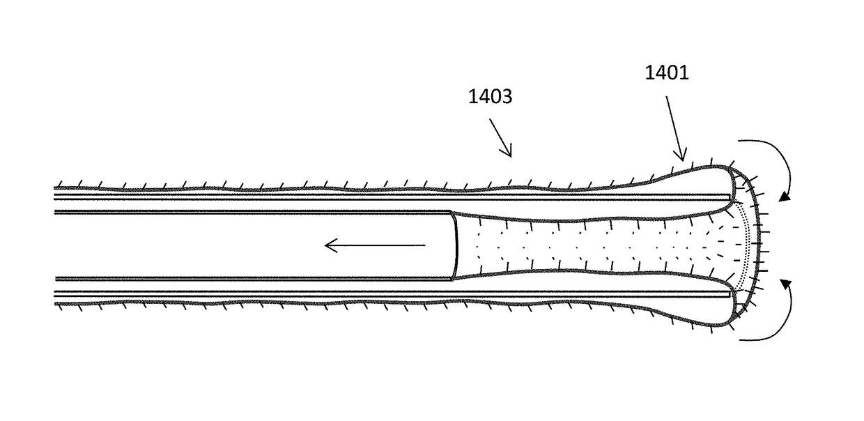
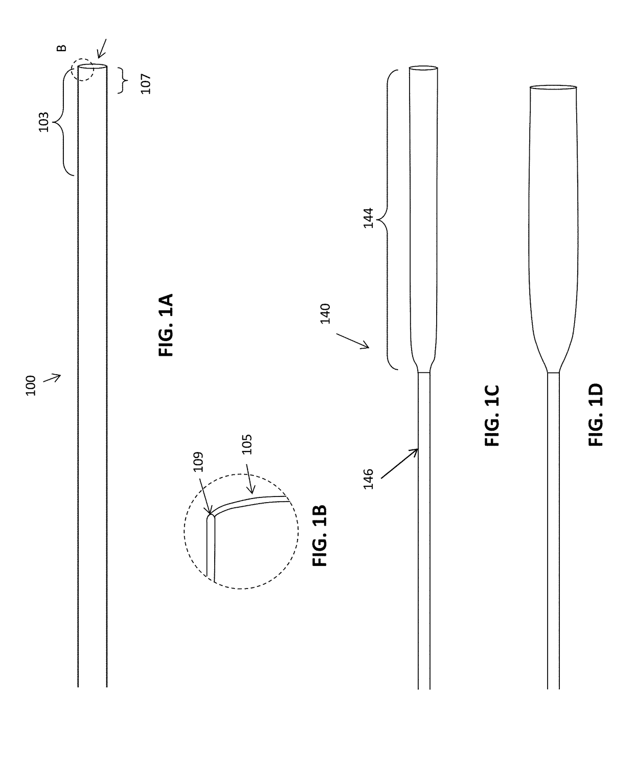
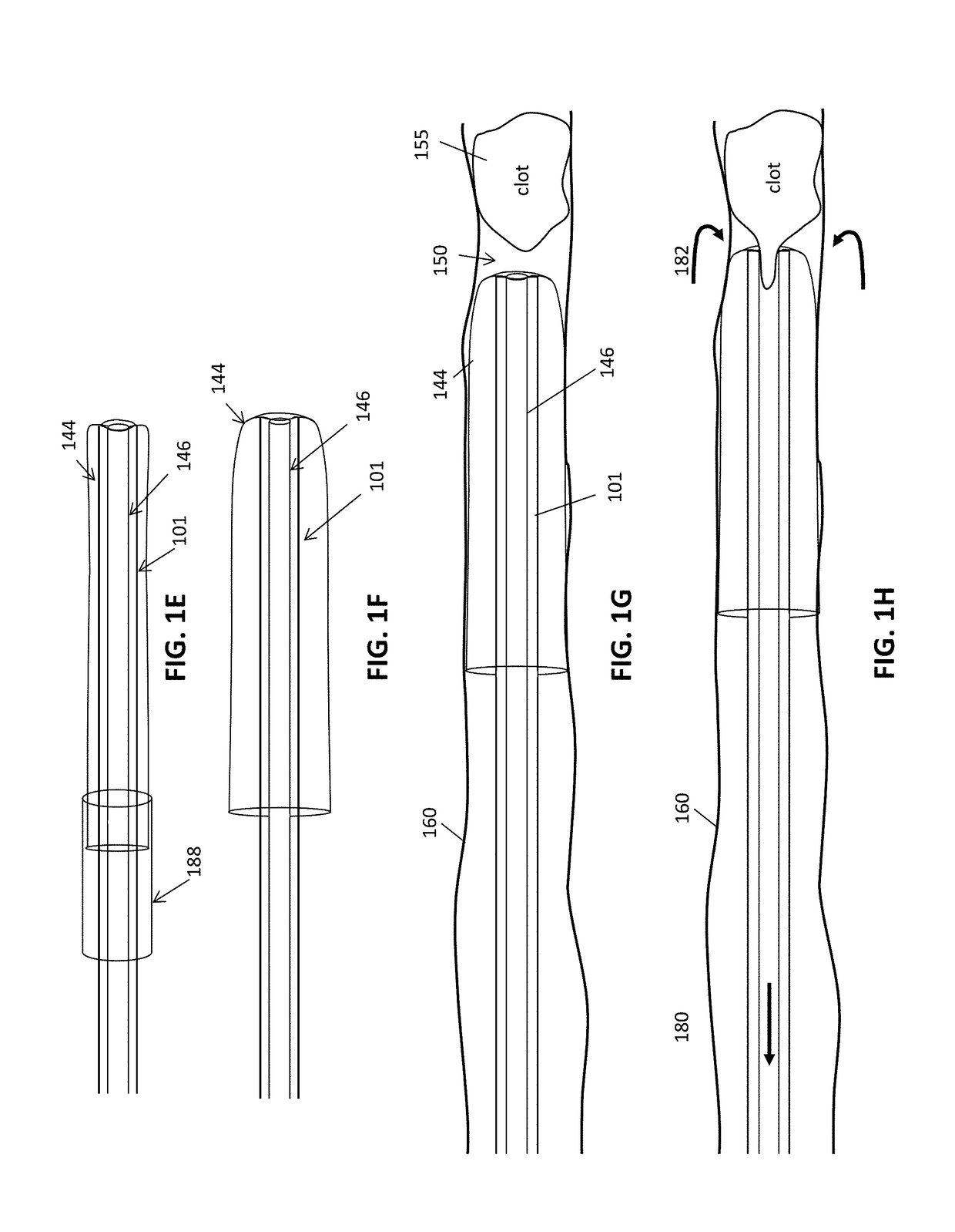
[0116]In general, described herein are mechanical thrombectomy apparatuses having an inverting tractor that is configured to prevent jamming and grab a blood clot. These apparatuses may include an elongate elongate inversion support support that supports an annulus over which the tractor inverts at the distal end. The tractor may comprise a flexible tube that doubles back over (e.g., inverts) over the distal end of the elongate inverting support (e.g., a catheter) so that it extends into the annuls opening of the elongate inverting support and an inner puller coupled to the inner end of the tractor that the tractor can be pulled proximally to pull and invert the tractor over the annulus at the distal end of the elongate inverting support to roll and capture a clot. The apparatus may include a guidewire lumen extending through the elongate inverting support, and / or tractor puller that is configured to pass a guidewire.

[0117]Any of the apparatuses described herein may be adapted to pr...


PUM

PropertyMeasurementUnit
Massaaaaaaaaaa
Massaaaaaaaaaa
Massaaaaaaaaaa

Abstract

Mechanical thrombectomy apparatuses that may be configured to prevent or reduce jamming (e.g., “anti-jamming” thrombectomy devices), grab clot, and/or macerate the thrombus, e.g., clot, being removed. These mechanical thrombectomy apparatuses may include a tractor comprising a flexible tube of material that inverts as it rolls over itself while being drawn into a catheter in a conveyor-like motion. In particular, described herein are mechanical thrombectomy apparatuses having tractors selectably extendable projections that may aid in grabbing and/or macerating a clot. Also described herein are seesawing tractors for mechanical thrombectomy apparatuses.

Description

CROSS REFERENCE TO RELATED APPLICATIONS[0001]This patent application claims priority to U.S. provisional patent application No. 62 / 327,024, filed on Apr. 25, 2016 and titled “DOZER THROMBECTOMY SYSTEM”; U.S. provisional patent application No. 62 / 345,152, filed on Jun. 3, 2016, and titled “DOZER THROMBECTOMY SYSTEM 2”; and U.S. provisional patent application No. 62 / 393,460, filed on Sep. 12, 2016, and titled “DOZER II THROMBECTOMY SYSTEM PROV”.[0002]This patent application may be related to U.S. patent application Ser. No. 15 / 291,015, filed on Oct. 11, 2016, titled “MECHANICAL THROMBECTOMY APPARATUSES AND METHODS”, which is a continuation of U.S. patent application Ser. No. 15 / 043,996, filed Feb. 15, 2016, now U.S. Pat. No. 9,463,035, which claims priority to each of the following provisional patent applications: U.S. Provisional Patent Application No. 62 / 284,300, filed Sep. 28, 2015; U.S. Provisional Patent Application No. 62 / 284,752, filed Oct. 8, 2015; and U.S. Provisional Patent ...

Claims


Application Information

Patent Timeline
IPC IPC(8): A61B17/22A61L29/08A61L29/14A61B17/3207
CPCA61B17/22031A61B17/320725A61B2017/22079A61L29/145A61L29/08A61M25/0074A61M25/0082A61B2017/22001A61B2017/22034A61B2017/22035A61B2017/22038A61M2210/12A61M2025/0079A61M2210/005A61B17/221A61B2017/00398A61B2017/2215A61B2017/3435A61B17/32075A61B2017/320064
Inventor WALLACE, MICHAEL P.GREENHALGH, E. SKOTTGARABEDIAN, ROBERT
Owner STRYKER CORP
Why Eureka
Try Eureka