Coil device

a coil and coil technology, applied in the direction of transformer/inductance details, transformer/inductance coil/winding/connection, electrical apparatus, etc., to achieve the effect of preventing a positional displacement problem

Active Publication Date: 2017-10-26
TDK CORPARATION
View PDF4 Cites 2 Cited by
  • Summary
  • Abstract
  • Description
  • Claims
  • Application Information

AI Technical Summary

Benefits of technology

The present invention is about preventing a positional displacement of an inner core with respect to an outer core in a coil device. The invention solves this problem by providing a coil device with a wire binding mechanism that bends and fixes the wires at both ends, making it difficult to generate a force in a direction where the inner core is rotated. Additionally, a support portion is added to prevent the force of moving or rotating the inner core when fixing the wires. The invention also includes a welding portion and a caulking portion for easily and quickly fixing the end of the wire, improving accuracy of fixed positions of the wire, inner core, and other components. Furthermore, the distance between the welding portion and the wirebound bottom portion is set to prevent positional displacement of the wire and inner core during bending of the welding portion.

Problems solved by technology

However, the shape of the wirebound portion in the prior art has a problem that a positional displacement of a center of the inner core to the outer core is generated at the time of pressing the end of the wire by the pressing portion of the wirebound portion.

Method used


Image

  • Coil device
  • Coil device
  • Coil device

Examples


Embodiment Construction

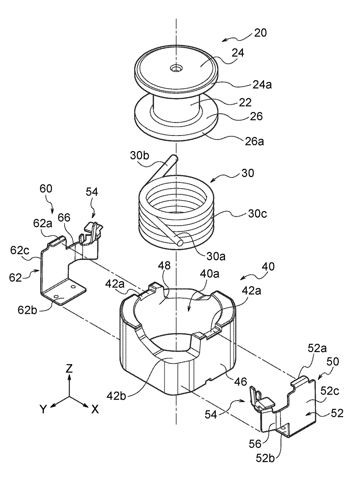
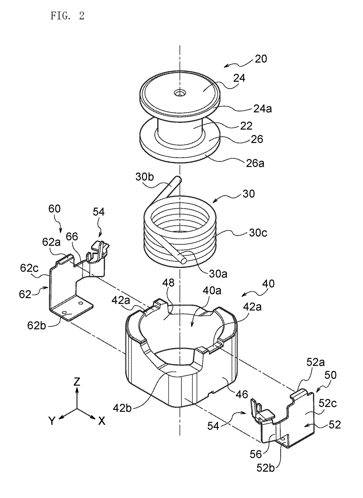
[0036]FIG. 1 is a whole perspective view of a coil device 10 according to First Embodiment of the present invention. The coil device 10 has an inner core 20 with a drum shape, a wire 30 winding around the inner core 20, an outer core 40 arranged on an outer periphery of the inner core 20, and a first terminal portion 50 and a second terminal portion 60 of a pair of terminal portions attached to the outer core 40. For example, the coil device 10 is mounted on a substrate or so in a state where a winding core 22 of the inner core 20 has an axial direction corresponding to a vertical direction to a mounting surface. In the following explanation, as shown in FIG. 1, the Z-axis direction is an axial direction of the winding core 22 of the inner core 20, and the X-axis direction and the Y-axis direction are directions perpendicular to the Z-axis. In the present specification, an upward direction means a positive direction of the Z-axis, and a downward direction means a negative direction ...


PUM


Abstract

A coil device includes an inner core having a winding core and a pair of flanges, a wire, an outer core arranged outside the inner core, a first terminal with a first wirebound having a first wirebound bottom arranged axially on a core end surface of the outer core and connected to a first end of the wire, and a second terminal with a second wirebound having a second wirebound bottom arranged on the core end surface and connected to a second end of the wire. The first wirebound has a first wire fixing portion bending from the first wirebound bottom toward a first rotating direction and fixing the first end. The second wirebound has a second wire fixing portion bending from the second wirebound bottom toward the same rotating direction as the first rotating direction and fixing the second end.

Description

BACKGROUND OF THE INVENTION1. Field of the Invention[0001]The present invention relates to a coil device, and in particular to a coil device provided with an inner core wound by a wire and an outer core arranged on an outer periphery of the inner core.2. Description of the Related Art[0002]The prior art proposes a coil device provided with an inner core constituted by a drum core wound by a wire and an outer core having a through hole housing the inner core. A terminal electrode electrically connected to an end of the wire is fixed to the outer core, and electric power is supplied to the wire of the drum core via the terminal electrode.[0003]There has been proposed a shape of the terminal electrode attached to the outer core having a fixing portion fixed to the outer core, a wirebound portion connected to the end of the wire, and a connection portion connecting the fixing portion and the wirebound portion. Furthermore, there has been proposed a preferable shape of the wirebound port...

Claims


Application Information

Patent Timeline
IPC IPC(8): H01F27/29H01F27/28
CPCH01F27/2823H01F27/292H01F3/14H01F27/263H01F27/2828
Inventor KOBAYASHI, KATSUMITAKANASHI, YOSHIYUKI
Owner TDK CORPARATION
Why Eureka
Try Eureka