LED tube lamp

Active Publication Date: 2017-10-26
JIAXING SUPER LIGHTING ELECTRIC APPLIANCE
View PDF19 Cites 25 Cited by
  • Summary
  • Abstract
  • Description
  • Claims
  • Application Information

AI Technical Summary

Benefits of technology

[0011]It's specially noted that the present disclosure may actually include one or more inventions claimed currently or not yet claimed, and for avoiding confusion due to unnecessarily distinguis

Problems solved by technology

However, existing LED tube lamps have certain drawbacks.
The LED chips spatially arranged on the circuit board inside the lamp tube are considered as spot light sources, and the lights emitted from these LED chips generally do not contribute uniform illuminance for the LED tube lamp without proper optical manipulation.
As a result, the entire tube lamp would exhibit a grainy or non-uniform illumination effect to a viewer of the LED tube lamp, thereby negatively affecting the visual comfort and even narrowing the viewing angles of the lights.
As a result, the quality and aesthetics requirements of average consumers would not be satisfied.
However, the disposition of the diffusion tube incurs an interface on the light transmission path to increase the likelihood of total reflection and therefore decrease the light outputting efficiency.
In addition, the optical rotatory absorption of the diffusion tube decreases the light outputting efficiency.
The heat dissipation of the power supply circuit in the small space of the end cap illustrated in the Chinese application is insufficient, therefore the power supply circuit is easier to be damaged.
Since the voltages and freq

Method used


Image

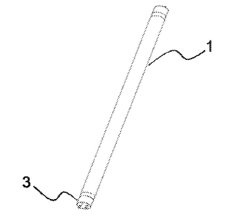
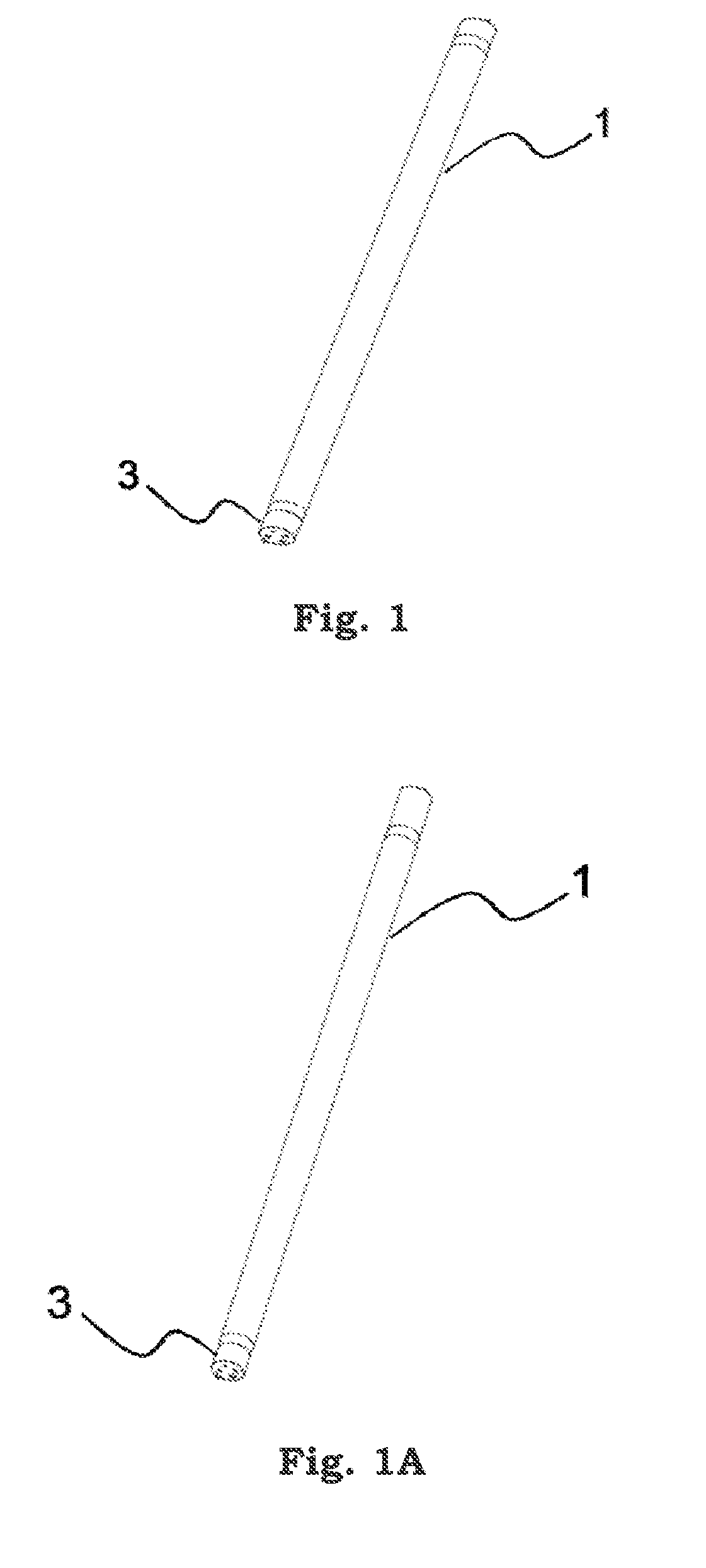
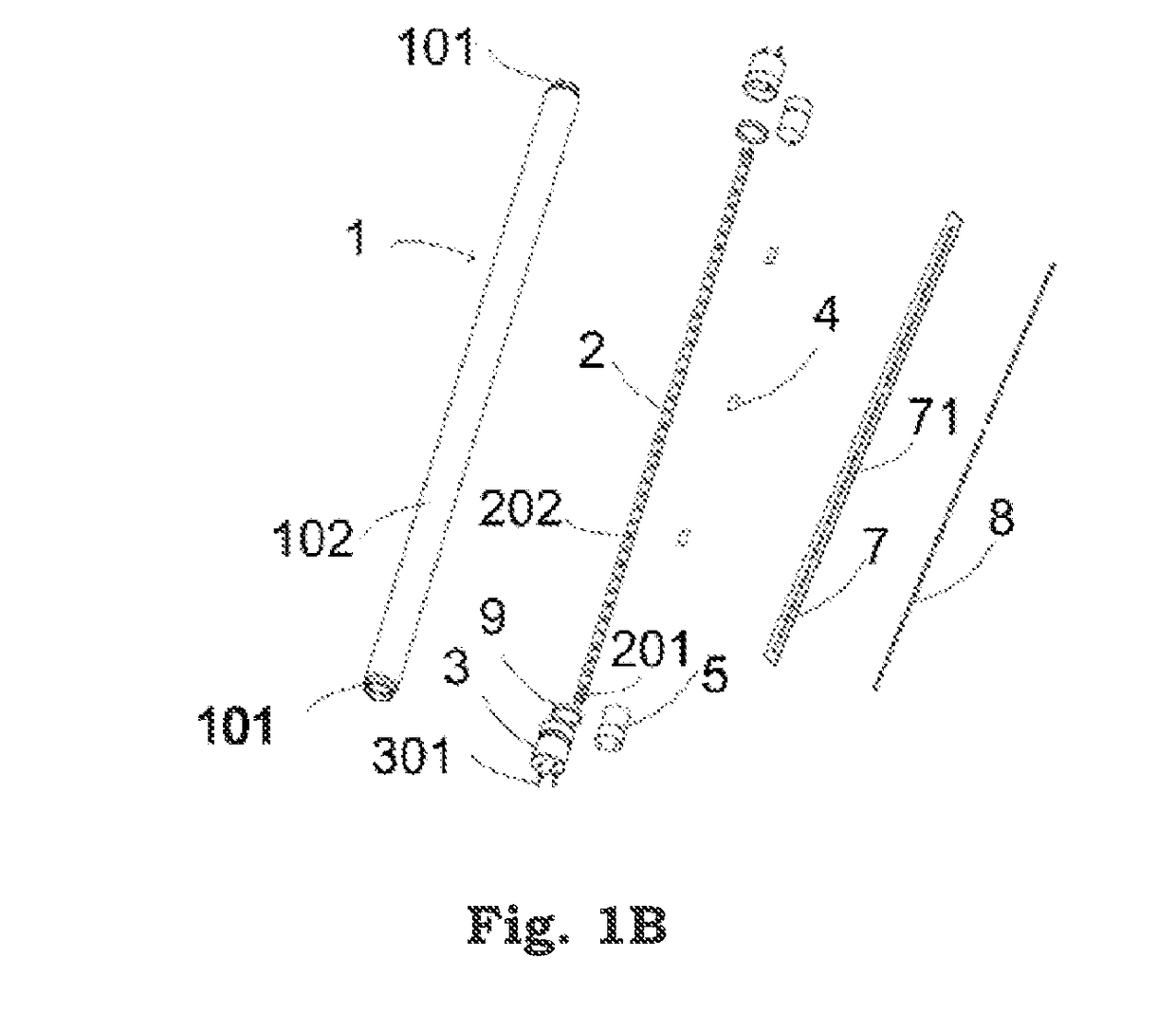
  • LED tube lamp
  • LED tube lamp
  • LED tube lamp

Examples


Embodiment Construction

[0156]The present disclosure provides a novel LED tube lamp. The present disclosure will now be described in the following embodiments with reference to the drawings. The following descriptions of various embodiments of this invention are presented herein for purpose of illustration and giving examples only. It is not intended to be exhaustive or to be limited to the precise form disclosed. These example embodiments are just that—examples—and many implementations and variations are possible that do not require the details provided herein. It should also be emphasized that the disclosure provides details of alternative examples, but such listing of alternatives is not exhaustive. Furthermore, any consistency of detail between various examples should not be interpreted as requiring such detail—it is impracticable to list every possible variation for every feature described herein. The language of the claims should be referenced in determining the requirements of the invention.

[0157]In...


PUM


Abstract

An LED tube lamp includes a lamp tube, a heat shrink sleeve covering on an outer surface of the lamp tube, an LED light strip fixed by an adhesive sheet to an inner circumferential surface of the lamp tube, a plurality of LED light sources on the LED light strip, two end caps respectively coupled to two opposite ends of the lamp tube, and a power supply circuit on the light strip. The LED light strip with the plurality of LED light sources and power supply circuit are in the lamp tube.

Description

CROSS-REFERENCE TO RELATED APPLICATIONS[0001]This application is a continuation-in-part application of U.S. application Ser. No. 15 / 298,955 filed on Oct. 20, 2016, U.S. application Ser. No. 15 / 055,630 filed on Feb. 28, 2016, U.S. application Ser. No. 15 / 339,221 filed on Oct. 31, 2016, U.S. application Ser. No. 15 / 258,068 filed on Sep. 7, 2016, U.S. application Ser. No. 15 / 211,783 filed on Jul. 15, 2016, and U.S. application Ser. No. 15 / 483,368 filed on Apr. 10, 2017, wherein the Ser. No. 15 / 298,955 application is a continuation application of U.S. application Ser. No. 14 / 865,387 filed in United States on Sep. 25, 2015, which itself claims Chinese priorities under 35 U.S.C. §119(a) of Patent Applications No. CN 201410507660.9 filed on Sep. 28, 2014; CN 201410508899.8 filed on Sep. 28, 2014; CN 201410623355.6 filed on Nov. 6, 2014; CN 201410734425.5 filed on Dec. 5, 2014; CN 201510075925.7 filed on Feb. 12, 2015; CN 201510104823.3 filed on Mar. 11, 2015; CN 201510134586.5 filed on Mar...

Claims


Application Information

Patent Timeline
IPC IPC(8): H05B33/08F21K9/27F21V23/00F21K9/278F21V23/02H05B44/00
CPCF21V23/009H05B33/0809F21V23/023F21K9/27H05B33/0812Y02B20/345F21K9/278H05B33/0845Y02B20/343F21V19/003H05B45/395H05B45/10Y02B20/30H05B45/3725H05B45/375H05B45/38H05B45/392H05B45/32
Inventor JIANG, TAOYE, QIFENGZHANG, YUEQIANG
Owner JIAXING SUPER LIGHTING ELECTRIC APPLIANCE
Why Eureka
Try Eureka