
Deployment system for deployable sofa, and deployable sofa

a deployment system and sofa technology, applied in the field of furniture, can solve the problems of high cost, low maintenance cost, and high manufacturing cost, and achieve the effects of improving the synchronicity of the deployment system, low manufacturing cost, and low maintenance cos

Inactive Publication Date: 2017-11-02
TAIZHOU AODE FURNITURE ACCESSORIES
View PDF2 Cites 0 Cited by
  • Summary
  • Abstract
  • Description
  • Claims
  • Application Information

AI Technical Summary

Benefits of technology

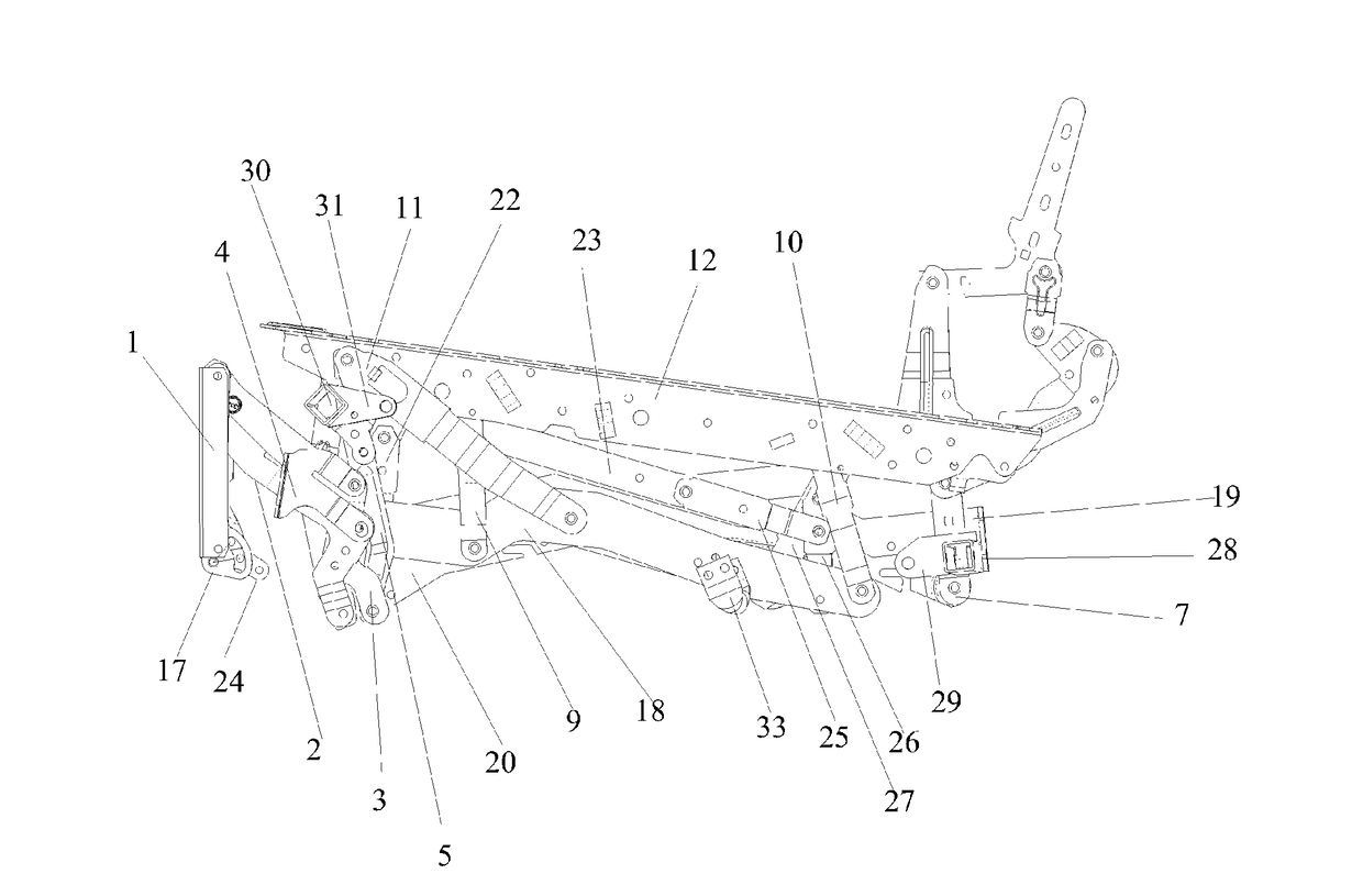
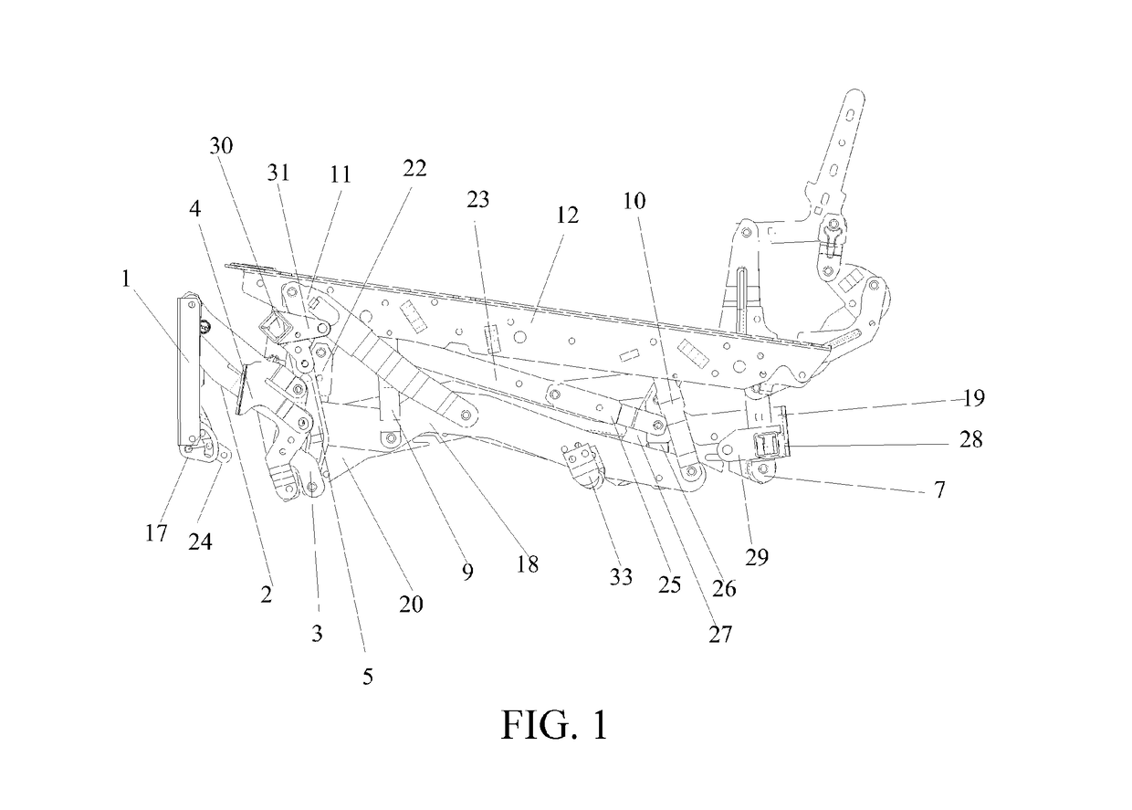
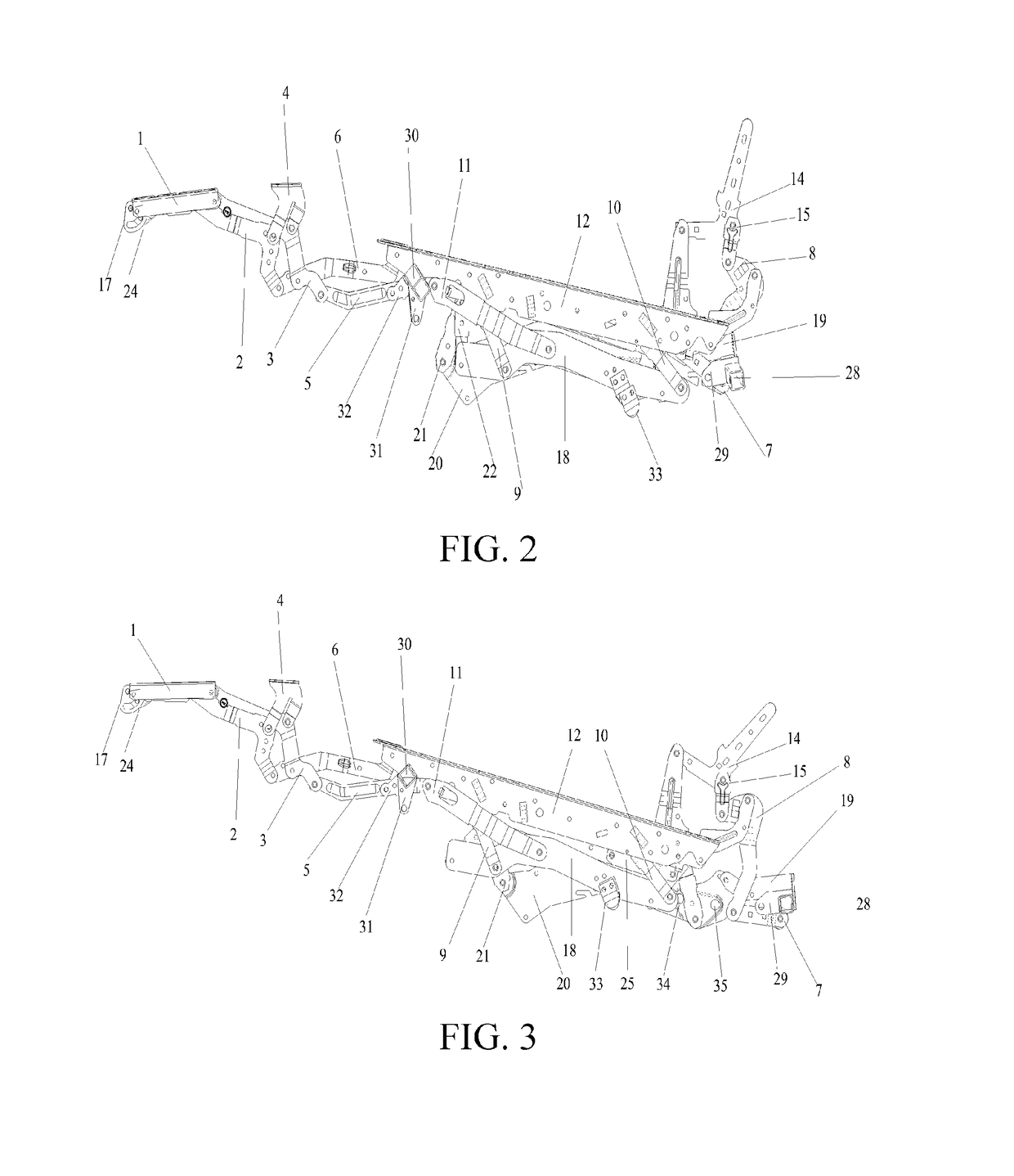
The present invention provides a deployment system for a deployable sofa that eliminates the jitter phenomenon and provides better synchronization during deployment. The system uses a support that moves parallel to the bottom fixing member and is connected to components that work together to achieve this. The use of a link rod mechanism can also improve synchronization, and the manufacturing and maintenance costs are both relatively low.

Problems solved by technology

However, sofa deployment apparatuses using the roller rail structures have some disadvantages: during mechanical deployment, there is a jitter phenomenon, and left and right mechanical deployment apparatuses have poor synchronicity, resulting in an impact on comfort of an electrical sofa; as compared with the link rod structures, a tighter tolerance is needed in production and manufacturing; during use, maintenance needs to be performed more frequently, and as compared with the link rod apparatuses, higher costs are needed.
In addition, use of a link rod mechanism can improve synchronicity of the deployment system, and manufacturing difficult and maintenance costs are both relatively low.

Method used


Image

  • Deployment system for deployable sofa, and deployable sofa
  • Deployment system for deployable sofa, and deployable sofa
  • Deployment system for deployable sofa, and deployable sofa

Examples


Embodiment Construction

[0045]The technical solutions in embodiments are clearly and completely described below with reference to the accompanying drawings in the embodiments of the present invention. Apparently, the described embodiments are merely some rather than all of the embodiments of the present invention. All other embodiments obtained by persons of ordinary skill in the art based on the embodiments of the present invention without creative efforts shall fall within the protection scope of the present invention.

[0046]In the description of the present invention, it should be understood that, location or position relationships indicated by the terms, such as “center”, “longitude”, “transverse”, “front”, “rear”, “left”, “right”, “vertical”, “horizon”, “top”, “bottom”, “inside”, and “outside”, are location or position relationships based on illustration of the accompanying drawings, are merely used for describing the present invention and simplifying the description instead of indicating or implying t...


PUM


Abstract

The present invention relates to a deployment system for a deployable sofa. The deployment system includes a deployment apparatus, and the deployment apparatus includes a bottom fixing member, a support, a swinging rod, a first multi-link rod mechanism, and a second multi-link rod mechanism, where the bottom fixing member is used to be fixedly mounted to a sofa bottom frame; the support is used to support a sofa seat; the swinging rod is rotatably connected to the support by means of the first multi-link rod mechanism, and the swinging rod is rotatably connected to the bottom fixing member by means of the second multi-link rod mechanism; the second multi-link rod mechanism is constructed to be capable of enabling the swinging rod to move approximately parallel to the bottom fixing member; and the first multi-link rod mechanism is constructed to be capable of transferring translation of the swinging rod to the support, to enable the support to move approximately parallel to the bottom fixing member. The present invention eliminates a jitter phenomenon during deployment of a deployable sofa, and a link rod mechanism is used to improve synchronicity and reduce manufacturing difficulty and maintenance fees.

Description

BACKGROUNDTechnical Field[0001]The present invention relates to the field of furniture, and in particular, to a deployment system for a deployable sofa, and a deployable sofa.Related Art[0002]Currently, existing deployment systems for deployable sofas use roller rail structures. The deployment systems for deployable sofas that use the roller rail structures are, to some extent, cheaper than mechanisms whose motion is provided depending on link rod apparatuses. However, sofa deployment apparatuses using the roller rail structures have some disadvantages: during mechanical deployment, there is a jitter phenomenon, and left and right mechanical deployment apparatuses have poor synchronicity, resulting in an impact on comfort of an electrical sofa; as compared with the link rod structures, a tighter tolerance is needed in production and manufacturing; during use, maintenance needs to be performed more frequently, and as compared with the link rod apparatuses, higher costs are needed.SUM...

Claims


Application Information

Patent Timeline
Patent Type & Authority Applications(United States)
IPC IPC(8): A47C20/10A47C17/04
CPCA47C17/04A47C20/10A47C1/0345A47C1/0355
Inventor XU, XIAOLIN
Owner TAIZHOU AODE FURNITURE ACCESSORIES
Features
  • Generate Ideas
  • Intellectual Property
  • Life Sciences
  • Materials
  • Tech Scout
  • Unparalleled Data Quality
  • Higher Quality Content
  • 60% Fewer Hallucinations
Learn More