Strain sensor

a strain sensor and sensor technology, applied in the field of strain sensors, can solve the problems of obstructing the improvement of the reliability of the pressure measuring mechanism, the difficulty in reducing the size of the combustion pressure sensor, and the failure of the pressure measurement mechanism to so as to reduce the overall size of the strain sensor, improve the reliability of the strength, and improve the degree of mechanical strength

Active Publication Date: 2017-11-02
DENSO CORP
View PDF5 Cites 4 Cited by
  • Summary
  • Abstract
  • Description
  • Claims
  • Application Information

AI Technical Summary

Benefits of technology

[0013]The advancement of the second housing in the mount hole will cause the second housing to leave the first housing, so that the tensile stress is exerted on the first housing and the second housing, thereby firmly holding the pressure measuring mechanism between the first face of the first housing and the second face of the second housing. The development of the tensile stress results in exertion of compressive stress on the pressure measuring mechanism through the first face and the second face. In this way, the installation of the strain sensor in the measuring target will create the tensile stress exerted on the first housing and the second housing and the compressive stress exerted on the pressure measuring mechanism. The tensile stress and the compressive stress are kept as they are after the strain sensor is installed in the measuring target.
[0014]When the strain sensor in a measuring operation to measure the compressive stress, and when the measuring target is compressed, it will cause the second housing which threadably engages the measuring target to be urged toward the first housing, thereby creating stress acting on the first housing and the second housing. This partially releases the tensile stress which has already acted on the first housing and the second housing after the strain sensor is installed in the measuring target. The absolute value of the stress acting on the first housing and the second housing, therefore, becomes small. This results in a decrease in required degree of mechanical strength of the first

Problems solved by technology

In use, a compressive stress which arises from the combustion pressure and occurs in the engine head is usually added to the housing in addition to the precompression, so that an absolute value of the compressive stress acting on the housing will become great, thus blocking improvement of the reliability of the housing.
The increase in mechanical strength of the housing usually requires an increase in size

Method used


Image

  • Strain sensor
  • Strain sensor
  • Strain sensor

Examples


first embodiment

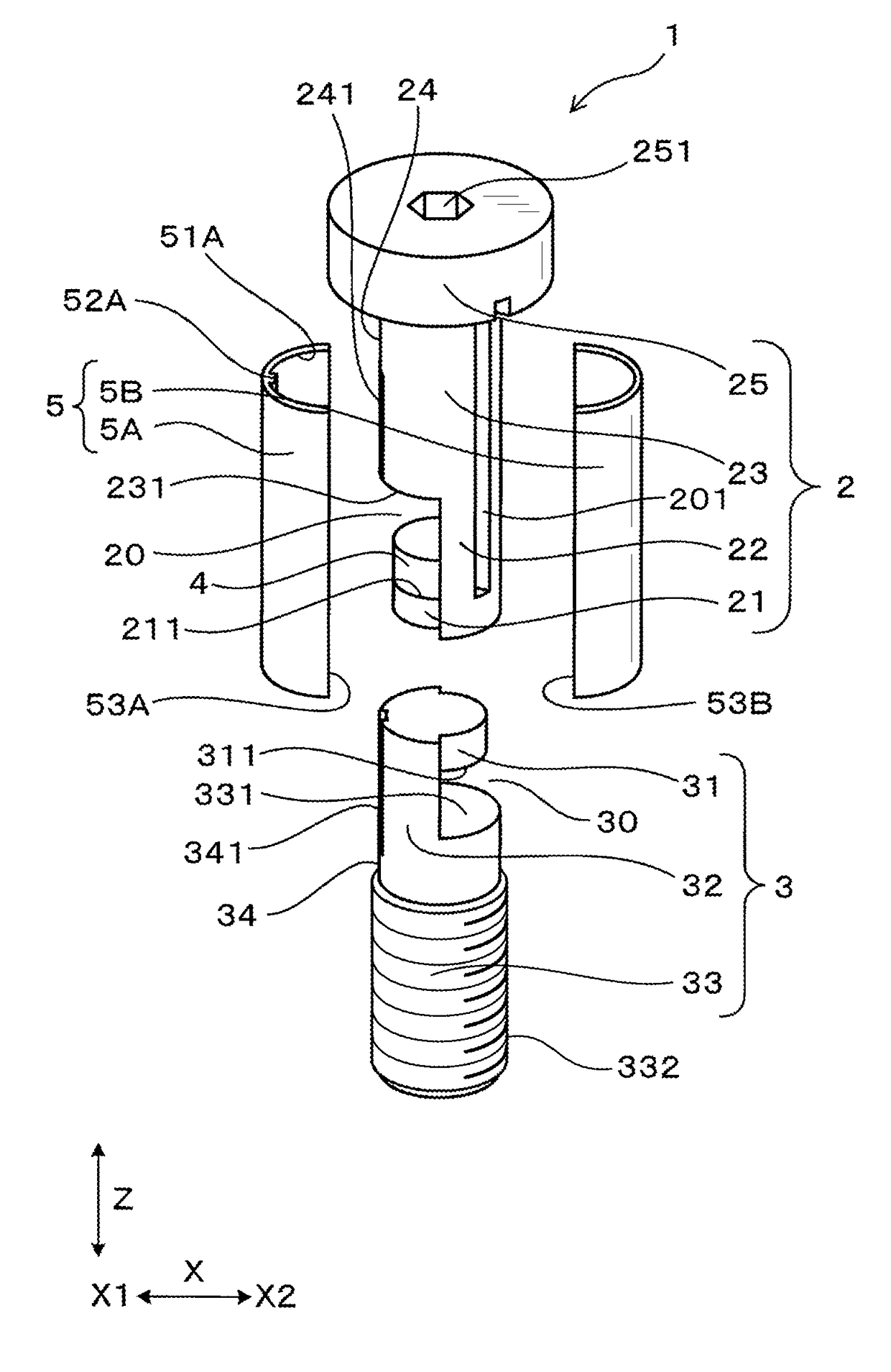
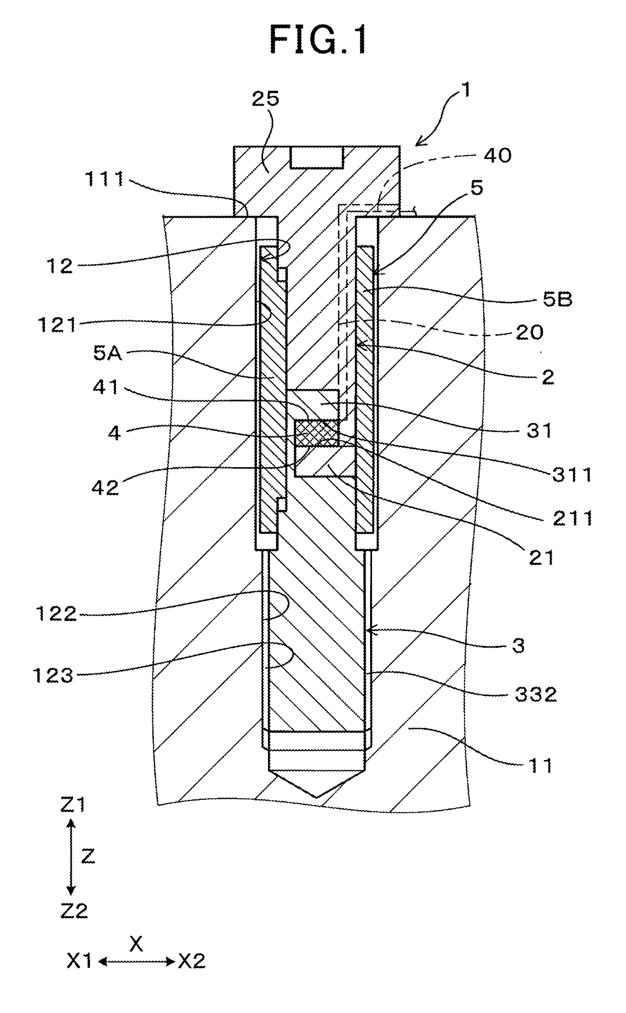
[0041]The strain sensor 1 according to the first embodiment will be described below with reference to FIGS. 1 to 6.

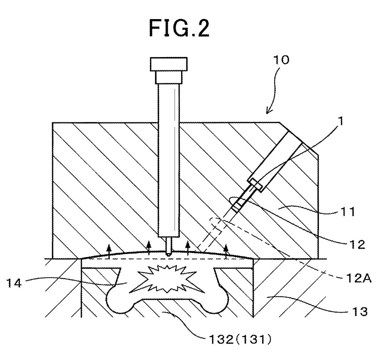
[0042]The strain sensor 1 is, as illustrated in FIG. 1, installed in the mount hole 12 with a bottom formed in the cylinder head 11 that is a measuring target. The strain sensor 1 works to measure the degree of compressive strain occurring in the cylinder head 11.

[0043]In the following discussion about the strain sensor 1, a direction parallel to a longitudinal center line of the mount hole 12 will be referred to as an axial direction Z. A region where there is an opening of the mount hole 12 in the axial direction Z of the strain sensor 1 will also be referred to as an opening side of the mount hole 12 or a base end side Z1, while a region where there is a bottom of the mount hole 12 in the axial direction Z of the strain sensor 1 will be referred to as a front end side Z2. The base end side Z1 and the front end side Z2 are also used for specifying locations of portion...

second embodiment

[0103]The strain sensor 1 of the second embodiment will be described below which has a modification of the holding mechanism which is made up of the first end portion 21 of the first housing 2 and the second end portion 31 of the second housing 3 and firmly holds the pressure measuring mechanism 4. In the second embodiment, the first extended portion 22 supporting the first end portion 21 and the second extended portion 32 supporting the second end portion 31 are different in structure from those in the first embodiment.

[0104]Referring to FIGS. 10 and 11, the front end side Z2 of the first housing 2 has two first extended portions 22 which face each other in the lateral direction X perpendicular to the axial direction Z of the strain sensor 1. The first end portion 21 is retained at two opposed sides thereof by ends of the first extended portion 22 in the form of a double fixed beam. The first housing 2 may alternatively be designed to have three or more extended portions 22. The ba...

third embodiment

[0109]The strain sensor 1 of the third embodiment will be described below which has a modification of the holding mechanism which is made up of the first end portion 21 of the first housing 2 and the second end portion 31 of the second housing 3 and firmly holds the pressure measuring mechanism 4. The strain sensor 1 of the third embodiment is designed to have the second housing 3 made up of two discrete members and firmly hold the pressure measuring mechanism 4 between the first end portion 21 of the first housing 2 and the second end portion 31 of the second housing 3 when the second housing 3 is assembled with the discrete members.

[0110]The first end portion 21 in this embodiment is, as illustrated in FIGS. 12 and 13, defined by a bottom of the center hole 26 formed in the first housing 2. The bottom is located on the front end side Z2 of the center hole 26. The first end portion 21 has formed therein the through-hole 27 extending through the thickness thereof. The hole 27 is sma...


PUM


Abstract

A strain sensor is provided which includes a strain sensor, a first housing, a second housing joined to the first housing, and a pressure measuring mechanism firmly retained between the first housing and the second housing. The pressure measuring mechanism is gripped between a first face of the first housing and a second face of the second housing to measure compressive stress exerted by a cylinder head of an internal combustion engine on the first housing and the second housing. This structure improves the reliability of mechanical strength of the housings and the pressure measuring mechanism and provides flexibility in selecting the type of the pressure measuring mechanism.

Description

CROSS REFERENCE TO RELATED DOCUMENT[0001]The present application claims the benefit of priority of Japanese Patent Application No. 2016-89829 filed on Apr. 27, 2016, the disclosure of which is incorporated herein by reference.BACKGROUND1 Technical Field[0002]The invention relates generally to a strain sensor which measures a compressive strain occurring in a given object.2 Background Art[0003]For instance, combustion pressure sensors for use in measuring the pressure in a combustion chamber of an internal combustion engine in which fuel is being combusted (which will also be referred to as a combustion pressure below) are known as strain sensors. Japanese Patent First Publication No. 2007-198169 discloses a combustion pressure sensor which includes a housing with a front end and a rear end (which will also be referred to as a base end below). The installation of the combustion pressure sensor in the internal combustion engine is achieved by placing the front end of the housing in co...

Claims


Application Information

Patent Timeline
IPC IPC(8): G01L23/10
CPCG01L23/10G01L1/16G01L5/0004
Inventor TAKEMOTO, SHOICHINAKANO, SHUICHIABE, NOBUYUKIITO, KENJI
Owner DENSO CORP
Why Eureka
Try Eureka