Stator for an electric motor and method for the production thereof

Inactive Publication Date: 2017-11-09
BROSE FAHRZEUGTEILE GMBH & CO KG HALLSTADT (DE)
View PDF23 Cites 5 Cited by
  • Summary
  • Abstract
  • Description
  • Claims
  • Application Information

AI Technical Summary

Benefits of technology

[0018]The advantages achieved with the invention include, for example, the fact that an additional adhesion of a stator star with radially outwardly directed stator teeth and a cylindrical stator yoke results in increased stiffness of a stator joined therefrom and that a particularly low body sound level in the electric motor is achieved during its intended electromotive application and motor operation. This in turn leads to a particularly low airborne sound level within a motor vehicle, in particular in the vehicle inter

Problems solved by technology

However, the technically advantageous separation between the star-shaped stator component, which is hereinafter referred to as stator star, and the (cylindrical) stator yoke as a further stator

Method used


Image

  • Stator for an electric motor and method for the production thereof
  • Stator for an electric motor and method for the production thereof
  • Stator for an electric motor and method for the production thereof

Examples


Embodiment Construction

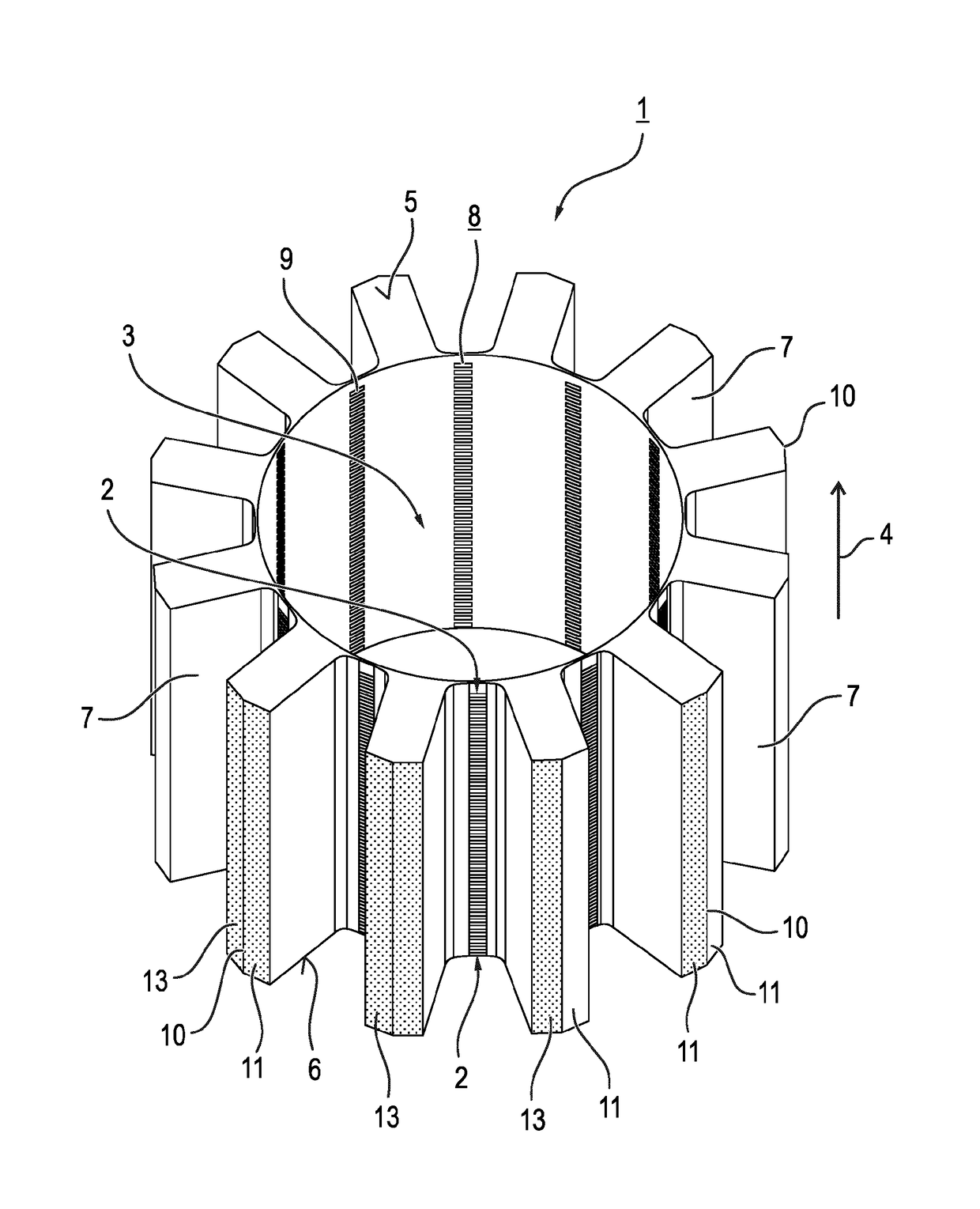
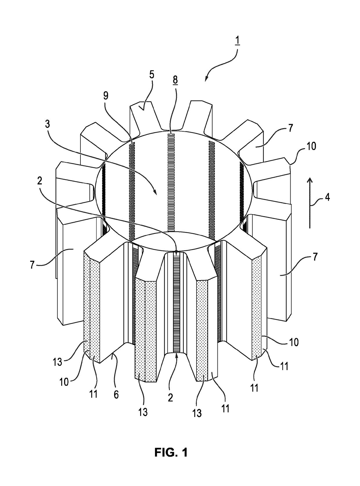
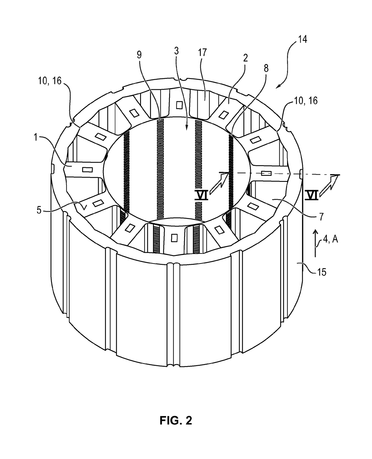
[0030]FIG. 1 shows a star-shaped stator component, which is hereinafter referred to as stator star 1, which in the exemplary embodiment is produced as a laminated core of stator laminations 2 stacked one above the other in layers. The stator laminations 2 are stacked on one another to form a central, cylindrical opening 3 in the stacking direction 4 and, for example, are stamped with one another. The stator star 1 is part of the unwound stator shown in FIG. 2, and the wound stator shown in FIG. 7, of an electric motor shown there. The laminated core of the stator core 1 terminates at the upper side 5 and lower side 6 of said stator core 1, preferably in each case with at least one stator plate 2 which is closed in the circumferential direction.

[0031]The stator star 1 comprises radially outwardly extending stator teeth 7, which form a cylindrical pole shoe 8 on the inner side located radially towards the center. The pole shoe 8, which faces the rotor of the electric motor shown in FI...


PUM


Abstract

A stator for an electric motor, in particular the steering motor of a motor vehicle, comprising a cylindrical stator yoke and a stator star joined therewith and having a number of radially outwardly directed stator teeth, the tooth tips thereof, in the assembly state, resting on the inner circumference of the stator yoke in corresponding connection points. The tooth tips on the stator star side, in the assembly state, in addition to being force-locked or frictionally locked with the connecting points on the stator yoke side in a press-fit, are also integrally bonded thereto.

Description

[0001]This nonprovisional application is a continuation of International Application No. PCT / EP2016 / 051280, which was filed on Jan. 22, 2016, and which claims priority to German Patent Application No. 10 2015 000 769.6, which was filed in Germany on Jan. 26, 2015, and which are both herein incorporated by reference.BACKGROUND OF THE INVENTIONField of the Invention[0002]The invention relates to a stator for an electric motor, in particular for a steering motor of a motor vehicle, comprising a cylindrical stator yoke and a stator star joined therewith and having a number of radially outwardly directed stator teeth, the tooth tips of which rest on corresponding connection points on the inner circumference of the stator yoke when in the joined state. It also relates to a method for producing such a stator, in particular of a steering motor of a motor vehicle.Description of the Background Art[0003]An electric motor comprises a stator forming the fixed motor part and a rotor forming the m...

Claims


Application Information

Patent Timeline
IPC IPC(8): H02K1/14H02K1/18H02K3/52H02K3/32H02K5/22
CPCH02K1/148H02K1/187H02K2213/03H02K3/522H02K5/225H02K3/325
Inventor BROHM, GERHARDKOCH, MATTHIASPSZOLA, PETERKURBEGOVIC-ZRNIC, JASMIN
Owner BROSE FAHRZEUGTEILE GMBH & CO KG HALLSTADT (DE)
Why Eureka
Try Eureka