Injection molding machine

a technology of injection molding machine and mold, which is applied in the field of injection molding machine, can solve the problems of reducing the life of the mold, preventing the smooth operation of the injection molding machine, and moving without being fixed, and achieves the effect of improving the durability of the mold

Active Publication Date: 2017-11-16
FANUC LTD
View PDF11 Cites 4 Cited by
  • Summary
  • Abstract
  • Description
  • Claims
  • Application Information

AI Technical Summary

Benefits of technology

[0017]According to the present invention, even in the case where a nozzle touch force is produced by means of the resilient force of a spring with a preload, control can be performed so that a predetermined nozzle touch force is produced to prevent resin leakage during injection and the nozzle touch force is reduced to such a degree that a mold does not leave a nozzle during mold opening, whereby deformation of the mold by the nozzle touch force can be suppressed to improve the durability of the mold.

Problems solved by technology

Unless the spring is used under a normal preload, as also described in Japanese Patent Application Laid-Open No. 2001-328140, its lifetime may be reduced or it may move without being fixed, thereby preventing smooth operation of the injection molding machine.
If the nozzle touch force is not larger than the preload of the spring, in this case, the spring cannot be compressed.
Thus, there is a problem that it is difficult to detect the nozzle touch force by the amount of compression of the spring.
Thus, the distortion cannot be detected by the strain sensor, so that the nozzle touch force cannot be accurately estimated.

Method used


Image

  • Injection molding machine
  • Injection molding machine
  • Injection molding machine

Examples


Embodiment Construction

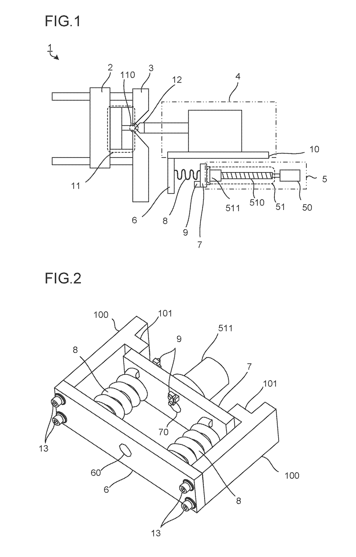
[0026]FIG. 1 is a schematic view showing a configuration of a principal part of an injection molding machine according to one embodiment of the present invention.

[0027]In an injection molding machine 1 according to the present embodiment, a drive compression member 7 is connected to a drive unit 5. A combination of a motor 50 and a ball screw 51, as shown in FIG. 1, or an oil-hydraulic pump may be used as the drive unit 5. In the injection molding machine 1 shown in FIG. 1, the drive unit 5 is provided with a ball screw shaft 510, which is connected to the motor 50, and the ball screw 51 comprising a ball screw nut 511 in threaded engagement with the ball screw shaft 510. As the ball screw nut 511 is secured to the drive compression member 7, the drive unit 5 and the drive compression member 7 are connected to each other.

[0028]Moreover, an injection base 10 is equipped with an injection device 4 and fixedly fitted with an injection compression member 6. A plurality of resilient memb...


PUM

PropertyMeasurementUnit
resilientaaaaaaaaaa
forceaaaaaaaaaa
resilient forceaaaaaaaaaa

Abstract

An injection molding machine is provided with a nozzle touch mechanism configured to press a nozzle attached to an injection device against a mold, a drive unit configured to move the injection device, a drive compression member connected to the drive unit, an injection compression member connected to the injection device, at least one resilient member interposed preloaded between the drive compression member and the injection compression member, and at least one strain sensor mounted on the drive compression member.

Description

BACKGROUND OF THE INVENTIONField of the Invention[0001]The present invention relates to an injection molding machine, and more particularly, to an injection molding machine capable of detecting and controlling a nozzle touch force not higher than the preload of a spring, in producing the nozzle touch force by means of the resilient force of the spring.Description of the Related Art[0002]In an injection molding machine comprising a mold clamping mechanism configured to apply a clamping force to a mold and an injection mechanism configured to inject a molten resin into the mold, it is necessary to press a nozzle, which is attached to the distal end portion of a cylinder for melting the resin, against the mold in order to inject the resin into the mold.[0003]In pressing the nozzle against the mold, the nozzle must be pressed with a predetermined force (nozzle touch force) lest the resin being injected leak out from between the nozzle and the mold. When the mold is open, in contrast, th...

Claims


Application Information

Patent Timeline
Patent Type & Authority Applications(United States)
IPC IPC(8): B29C45/76B29C45/17
CPCB29C45/76B29C45/1777B29C2945/76217B29C2945/76006B29C2945/76381B29C2945/76481B29C2945/76498B29C2945/76695B29C2945/76859B29C2045/1778
Inventor HIROSE, DAISUKENISHIMURA, KOICHI
Owner FANUC LTD
Why Eureka
Try Eureka