Wire harness attachment structure and wiring unit

Active Publication Date: 2017-11-16
AUTONETWORKS TECH LTD +2
View PDF10 Cites 2 Cited by
  • Summary
  • Abstract
  • Description
  • Claims
  • Application Information

AI Technical Summary

Benefits of technology

[0008]According to the present design, the plate and the cover are pressed against each other, and thus the cover is fixed to the plate and the wire harness is attached to

Problems solved by technology

Therefore, there is a problem in th

Method used


Image

  • Wire harness attachment structure and wiring unit
  • Wire harness attachment structure and wiring unit
  • Wire harness attachment structure and wiring unit

Examples


Example

[0018]The following describes preferred embodiments.

[0019]In the wire harness attachment structure according to the present design, the cover may include a plurality of covers that have different shapes. With such a configuration, a cover can be selected out of the plurality of covers as appropriate according to a mode in which the wire harness is to be mounted.

[0020]Also, in the wire harness attachment structure according to the present design, the lock receiving portion of the plate may be provided in a plurality, and any covers that are selected out of the plurality of covers as appropriate can be fixed to the plate. With such a configuration, it is possible to change the mode in which the wire harness is to be mounted, by fixing covers selected out of the plurality of covers as appropriate, to the plate. Therefore, there is no need to provide a dedicated cover for each of the wiring units of different types, and it is relatively easy to support wiring units of many types.

[0021]A...


PUM


Abstract

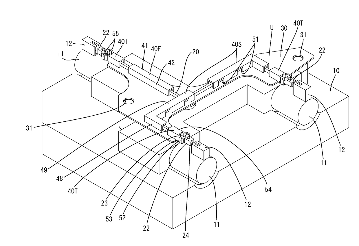
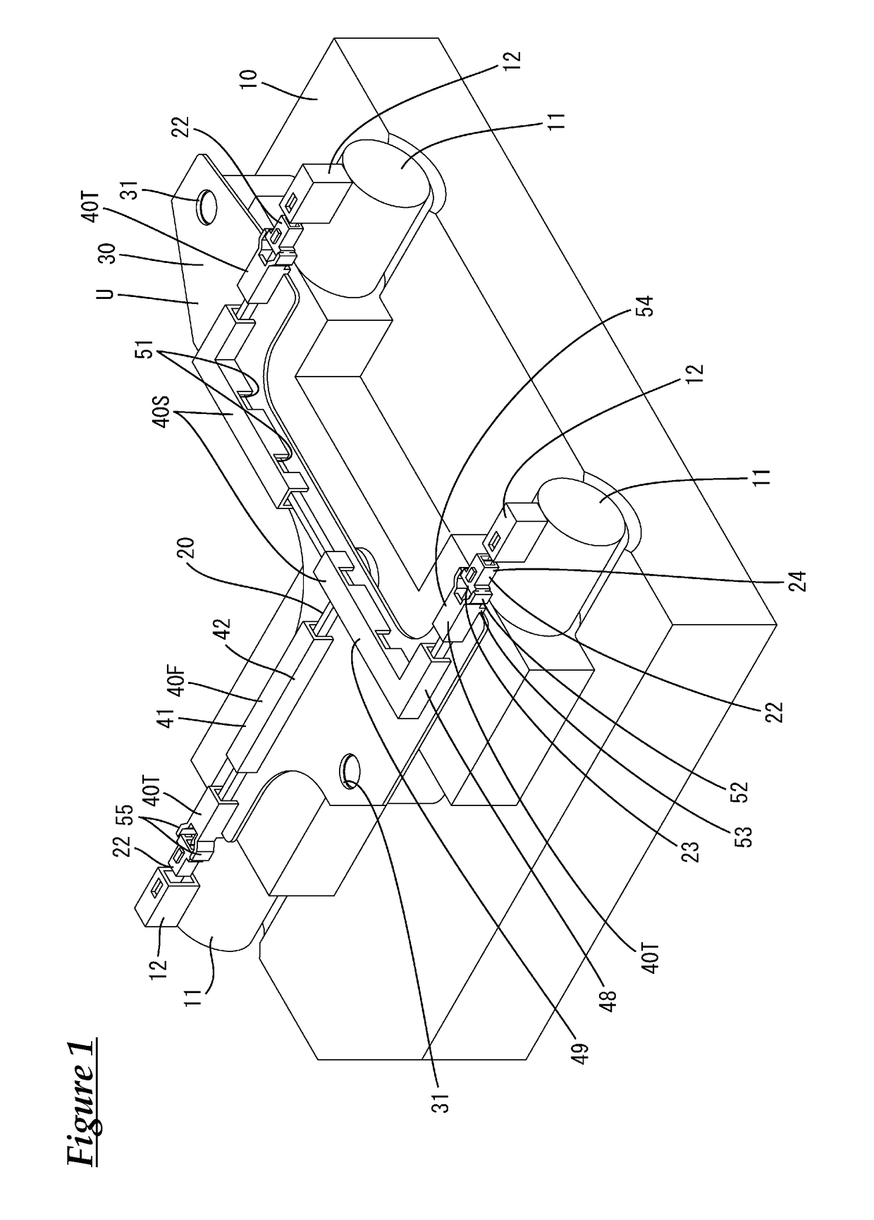
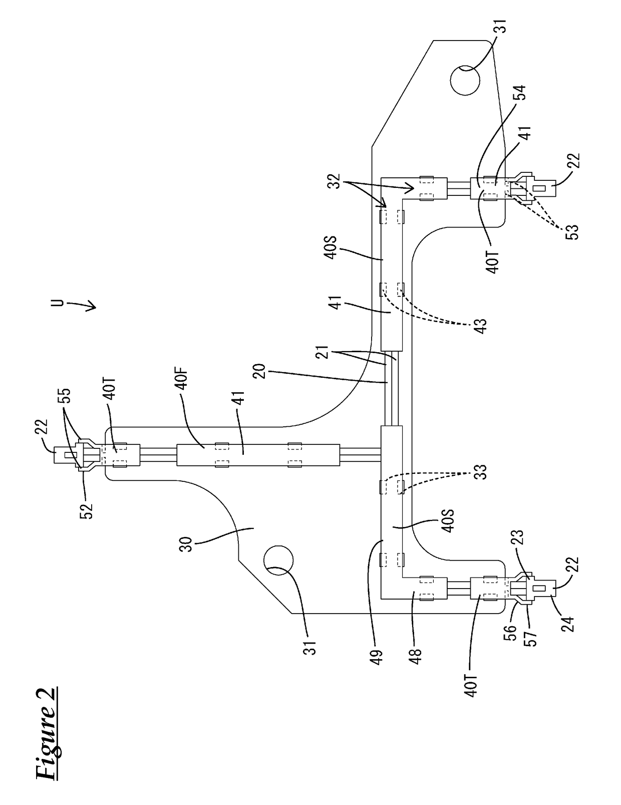
A wire harness attachment structure and a wiring unit that are capable of reducing the amount of work that is needed when attaching a wire harness. The wire harness attachment structure includes: a plate on which a wire harness is to be mounted; and a cover that covers a portion of the wire harness and is fixed to the plate. A locking portion that is provided for the cover is configured to be orientated to face, and to be inserted into, a lock receiving portion that is provided for the plate, and thus the locking portion is locked to the lock receiving portion, and the cover is fixed to the plate.

Description

CROSS REFERENCE TO RELATED APPLICATIONS[0001]This application claims the priority of Japanese patent application JP2014-244632 filed on Dec. 3, 2014, the entire contents of which are incorporated herein.TECHNICAL FIELD[0002]The present invention relates to a wire harness attachment structure and a wiring unit.BACKGROUND ART[0003]There are conventionally known wiring units in which a wire harness is fixed to a plate. For example, in the wiring unit that is disclosed in Patent Document 1 (JP 2014-199071A) below, a wire harness is mounted on a plate and is fixed to the plate at a plurality of positions using cable ties. A cable tie is passed through a pair of pass-through holes that are formed penetrating the plate and is locked to the back surface side of the plate, to tie up the wire harness on the top surface side of the plate.SUMMARY[0004]However, with the above-described configuration, in order to attach the wire harness to the plate, it is necessary to perform the task of passing...

Claims


Application Information

Patent Timeline
IPC IPC(8): B60R16/023B60R16/02H01R24/00
CPCB60R16/0231B60R16/0207H01R24/005H01R2201/26B60R16/0215H01R13/73F16H61/0006
Inventor SONE, KOSUKETANAKA, TETSUJINAKAYAMA, OSAMUMAKI, TOMOHIDE
Owner AUTONETWORKS TECH LTD
Why Eureka
Try Eureka