

Imaging apparatus and method for controlling the same
- Summary
- Abstract
- Description
- Claims
- Application Information
AI Technical Summary
Benefits of technology
Problems solved by technology
Method used
Image

Examples
first embodiment
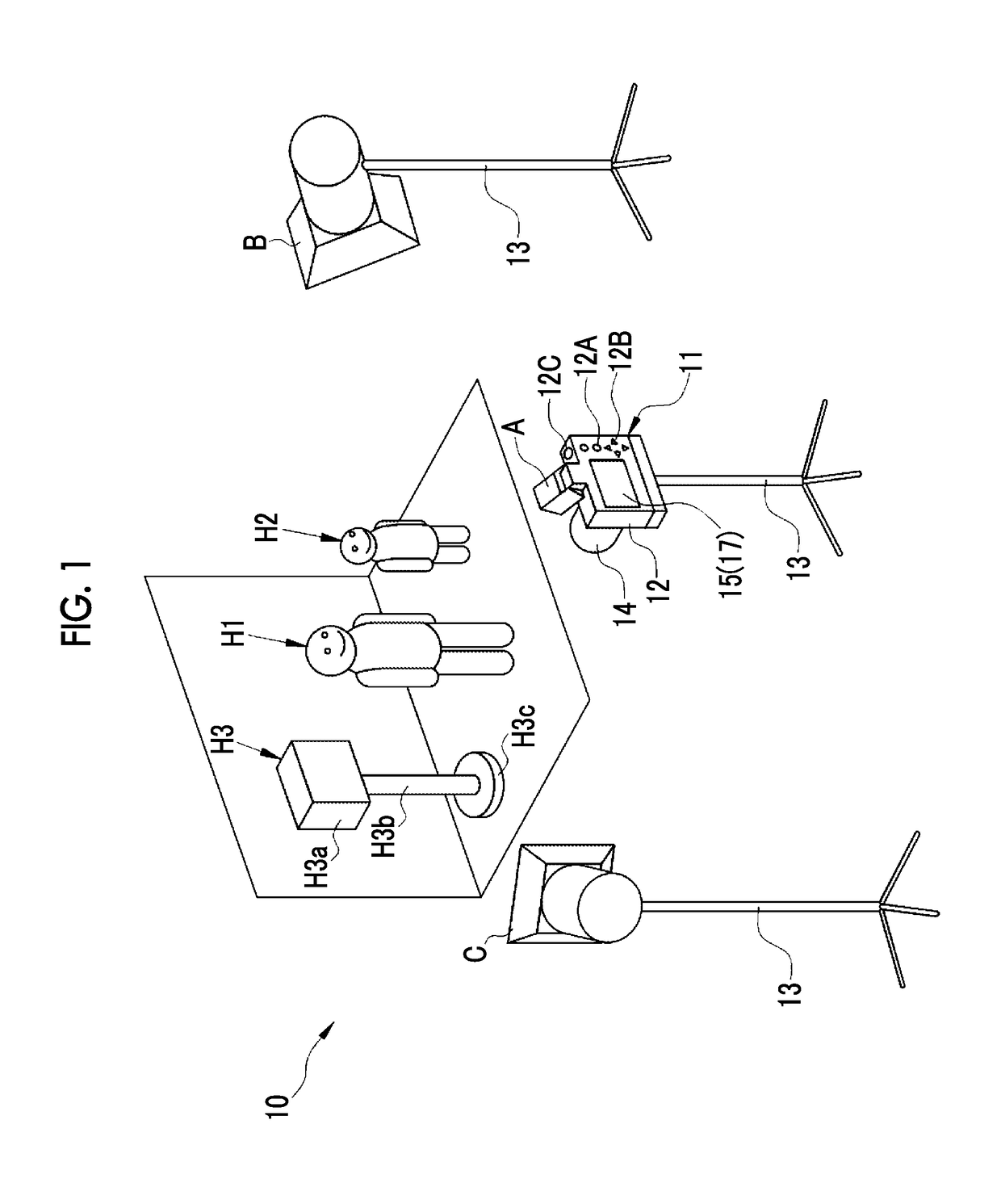
[0040]An imaging system 10 illustrated in FIG. 1 is used to capture images in a studio in which identification photographs or commemorative images are taken. The imaging system 10 includes a digital camera 11 which is an imaging apparatus and a plurality of illuminating devices A to C. The illuminating devices A to C correspond to at least two illuminating devices, that is, first and second illuminating devices in the claims. In this example, three illuminating devices, that is, the first to third illuminating devices are provided. However, three or more illuminating devices may be provided.
[0041]The digital camera 11 has a camera body 12 in which the illuminating device A which is a built-in strobe device is provided. The illuminating devices B and C are independent illuminating devices that are independent of the digital camera 11 and are independent strobe devices in this embodiment. The digital camera 11 and the illuminating devices B and C are provided while being supported by ...
second embodiment
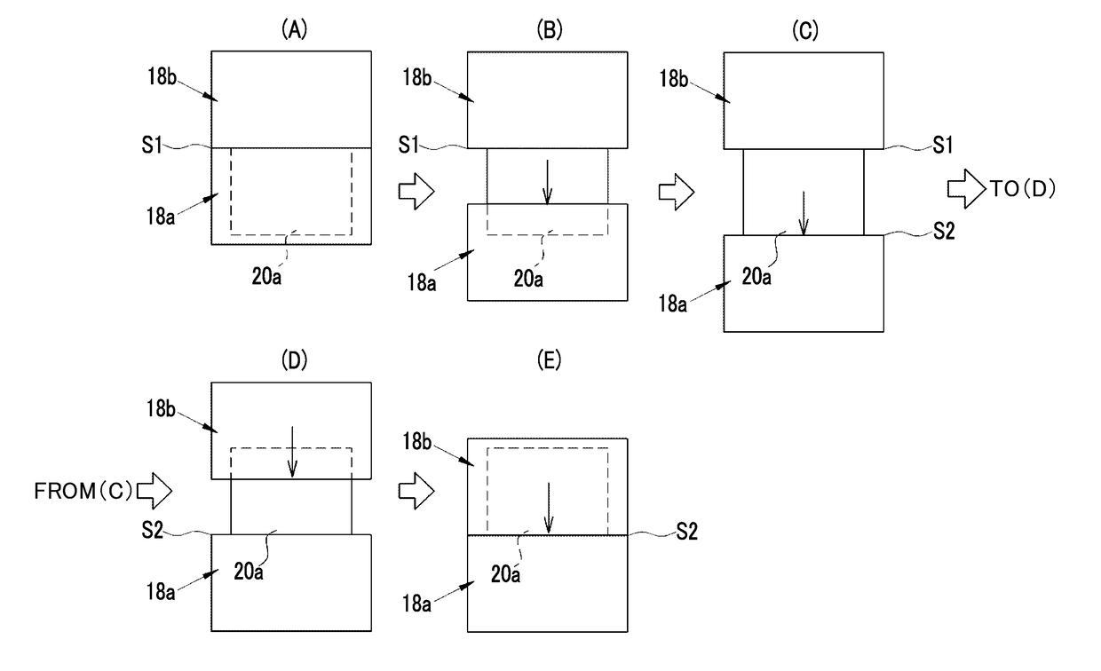
[0099]In the first embodiment, the example in which the shutter front curtain 18a and the shutter rear curtain 18b are driven at a constant speed all the time regardless of the shutter speed has been described. However, the invention is not limited thereto. In the following second embodiment, a curtain speed adjustment mechanism is provided which automatically adjusts the traveling speed of the shutter front curtain 18a and the shutter rear curtain 18b, that is, a curtain speed. Therefore, the shutter 18 has a function of changing the transition period for which the partial exposure region is transferred in the imaging area 20a. In this case, the curtain speed adjustment mechanism may be provided in the shutter driving mechanism 19 that drives the shutter 18. For example, the curtain speed adjustment mechanism has the same configuration as that disclosed in JP2001-235779A. The configuration of the second embodiment is the same as the configuration of the first embodiment except that...
PUM
 Abstract
Description
Claims
Application Information