Method and apparatus for designing dental prosthetic device

Pending Publication Date: 2021-08-05
SHOFU INC
View PDF0 Cites 0 Cited by
  • Summary
  • Abstract
  • Description
  • Claims
  • Application Information

AI Technical Summary

Benefits of technology

[0136]According to the design method and the design apparatus of the first embodiment of the present invention, the following effects can be achieved.
[0137]The dental prosthetic device design method includes the acquisition step ST1, the determination step ST2, the readout step ST3, the selection step ST4, the placement step ST5, and the creation step ST6. The acquisition step ST1 acquires scan data of maxillary and mandibular dentitions. The determination step ST2 determines a tooth restoration site based on the scan data. The readout step ST3 reads out plural pieces of attrition shape data of a tooth related to the restoration site, from the maxillary and mandibular tooth shape data sets having plural pieces of attrition shape data S0 to S4 with different degrees of attrition for each tooth of the maxillary and mandibular dentitions. The selection step ST4 selects attrition shape data from among the plural pieces of attrition shape data, in accordance with the degrees of attrition of the maxillary and mandibular dentitions. The placement step ST5 places the selected attrition shape data at the restoration site. The creation step ST6 creates shape data of the dental prosthetic device from the attrition shape data placed at the restoration site.
[0138]By virtue of such a configuration, the dental prosthetic device can be designed based on the attrition shape data selected in accordance with the degrees of attrition. It is hereby possible to reduce the amount of work for designing the dental prosthetic device and to shorten the work time, enabling the dental prosthetic device to be efficiently designed.
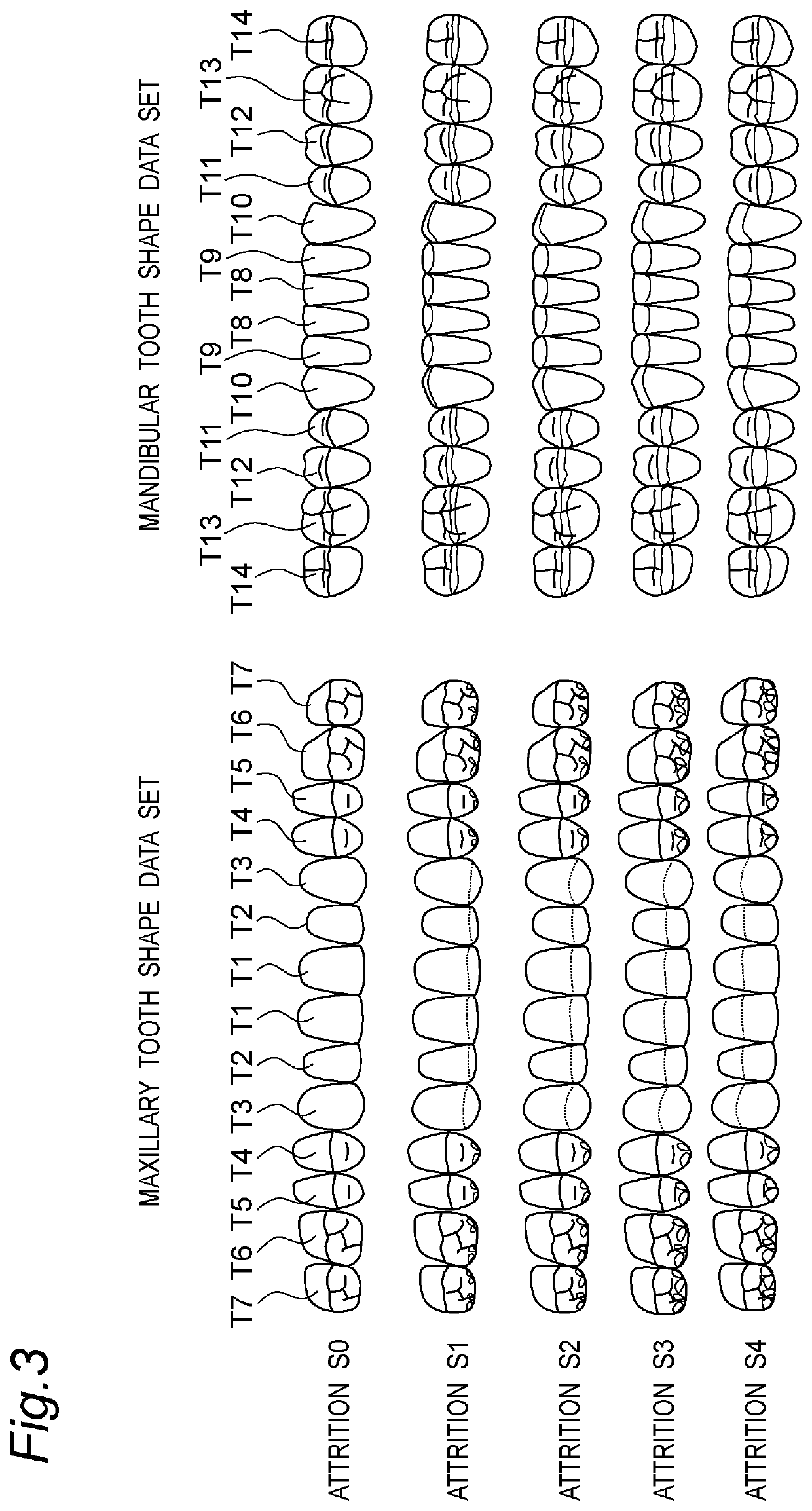
[0139]The plural pieces of attrition shape data include plural pieces of tooth shape data in which the attrition portion is drilled stepwise from the crown side toward the root side, for each of a plurality of teeth. Such a configuration can accommodate the intraoral environment of various patients. For example, it can handle from the maxillary and mandibular dentitions of a patient with a large degree of attrition to the maxillary and mandibular dentitions of a patient with a small degree of attrition. This makes it possible to design the dental prosthetic device more efficiently.
[0140]The maxillary and mandibular tooth shape data sets include maxillary tooth shape data and mandibular tooth shape data. The maxillary tooth shape data includes shape data of the upper central incisor T1, the upper lateral incisor T2, the upper canine T3, the upper first premolar T4, the upper second premolar T5, the upper first molar T6, and the upper second molar T7. The mandibular tooth shape data includes shape data of the lower central incisor T8, the lower lateral incisor T9, the lower canine T10, the lower first premolar T11, the lower second premolar T12, the lower first molar T13, and the lower second molar T14. Such a configuration enables the dental prosthetic device to be designed more efficiently.
[0141]The maxillary tooth shape data has plural pieces of attrition shape data for each of the upper central incisor T1, the upper lateral incisor T2, the upper canine T3, the upper first premolar T4, the upper second premolar T5, the upper first molar T6, and the upper second molar T7. In the plural pieces of attrition shape data of the upper central incisor T1, its lingual surface in contact with the opposing tooth is drilled stepwise within the range of 0.00 mm or more and 1.50 mm or less from the crown side toward the root side. In the plural pieces of attrition shape data of the upper lateral incisor T2, its lingual sur

Problems solved by technology

The tooth shape data used for design of the dental prosthetic device using CAD, however, does not take the degree of attrition into consideration.
This results in a problem that the dental prosthesis cannot be designed efficiently.
For example, there is a problem that as the amount of work increases, the de

Method used


Image

  • Method and apparatus for designing dental prosthetic device
  • Method and apparatus for designing dental prosthetic device
  • Method and apparatus for designing dental prosthetic device

Examples


Example

[0193]In Example 1 and Comparative Example 1, the shape data of the crown of the upper first molar T6 was designed. In Example 2 and Comparative Example 2, the shape data of the crown of the lower first molar T13 was designed. In Example 1, the crown was designed under the same conditions as in Comparative Example 1 except that the design was performed using the attrition shape data. In Example 2, the crown was designed under the same conditions as in Comparative Example 2 except that the design was performed using the attrition shape data.

[0194]The thus designed data is subjected to a shape alignment with scan data of a wax pattern on a crown made by a dental technician with 10 years of experience and then to a 3D surface deviation analysis. Hereinafter, the scan data of the wax pattern on the crown made by the dental technician with 10 years of experience is referred to as “reference data”. The results of the surface deviation analysis are shown in FIGS. 28 to 31 and Tables 1 and ...


PUM


Abstract

A dental prosthetic device design method according to an aspect of the present invention is a method for designing a dental prosthetic device by a computer, the method including: acquiring scan data of maxillary and mandibular dentitions; determining a restoration site of a tooth, based on the scan data; reading out plural pieces of attrition shape data of a tooth related to the restoration site, from maxillary and mandibular tooth shape data sets having plural pieces of attrition shape data with different degrees of attrition for each tooth of the maxillary and mandibular dentitions; selecting attrition shape data from among the plural pieces of attrition shape data, in accordance with the degrees of attrition of the maxillary and mandibular dentitions; placing the selected attrition shape data at the restoration site; and creating shape data of a dental prosthetic device from the attrition shape data placed at the restoration site.

Description

BACKGROUND OF THE INVENTION1. Field of the Invention[0001]The present invention relates to a method and an apparatus for designing a dental prosthetic device.2. Description of the Related Art[0002]Japanese Laid-Open Patent Publication No. 10-75963 discloses a method for designing, on a computer, a dental prosthesis model such as a bridge and a crown by use of the computer. In the method described in Japanese Laid-Open Patent Publication No. 10-75963, a pontic model corresponding to each tooth shape is created, saved in a database, and used to design the dental prosthesis model such as the crown and the bridge.[0003]The method described in Japanese Laid-Open Patent Publication No. 10-75963, however, still has room for improvement in terms of efficiently designing dental prostheses.SUMMARY OF THE INVENTION[0004]It is therefore an object of the present invention to provide a design method and a design apparatus capable of designing a dental prosthesis efficiently.[0005]A dental prosthe...

Claims


Application Information

Patent Timeline
IPC IPC(8): A61C5/77A61C13/00A61C5/30A61C5/20
CPCA61C5/77A61C5/20A61C5/30A61C13/0004
Inventor TAKADA, HAJIMEINOUE, TOMOYUKI
Owner SHOFU INC
Why Eureka
Try Eureka