
System and Method for Onboard Wake and Clear Air Turbulence Avoidance

a technology of clear air turbulence and system and method, which is applied in the direction of energy-efficient board measures, instruments, transportation and packaging, etc., can solve the problems of significant losses in annual revenue for the aviation industry, difficult for aircraft pilots to detect and avoid clear air turbulence, and especially hazardous wake turbulen

Active Publication Date: 2017-11-23
NASA
View PDF6 Cites 16 Cited by
  • Summary
  • Abstract
  • Description
  • Claims
  • Application Information

AI Technical Summary

Benefits of technology

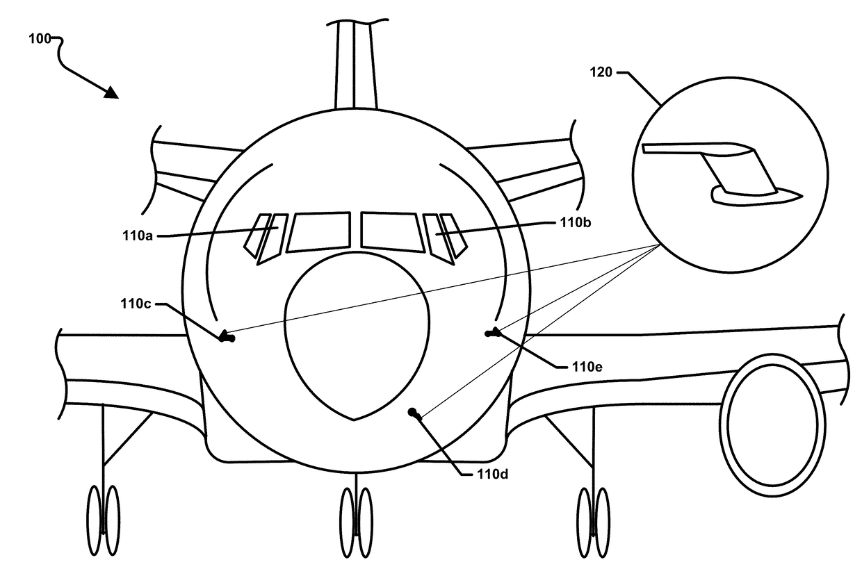
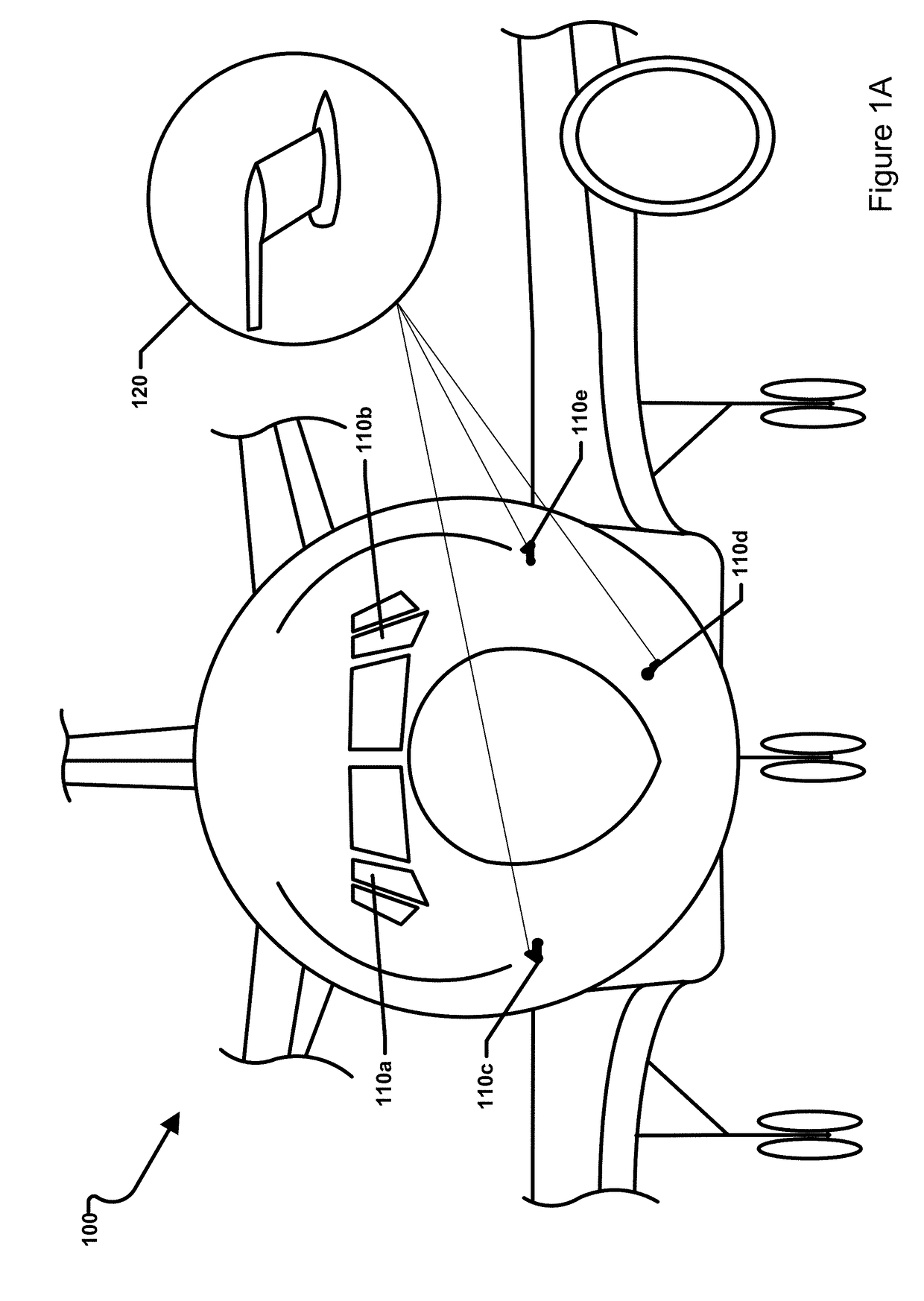
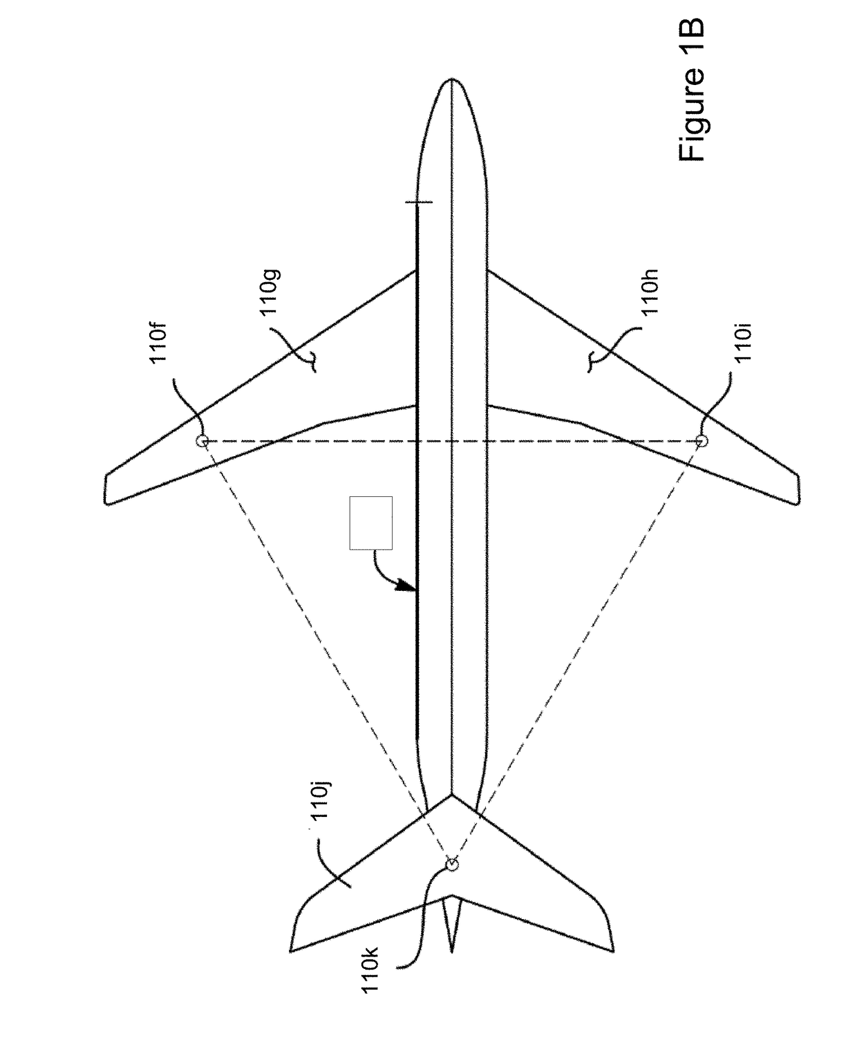
The patent describes a system that uses infrasonic sensors on an aircraft to detect air turbulence. This can include both natural and man-made turbulence, such as wake turbulence, clear air turbulence, mountain waves, and severe weather. The system can also detect events like a rocket launch. Overall, the system allows for passive detection of air turbulence and helps avoid potential safety risks for aircraft.

Problems solved by technology

Clear air turbulence (also referred to as “CAT”) is a leading cause of in-flight injuries and in severe cases can result in fatalities, resulting in significant losses in annual revenue to the aviation industry.
Clear air turbulence is usually impossible to detect with the naked eye and very difficult to detect with conventional radar, making it difficult for aircraft pilots to detect and avoid clear air turbulence.
Wake turbulence is especially hazardous in the region behind an aircraft in the takeoff or landing phases of flight.
These aircraft separation standards result in delays that limit the volume of takeoffs and landings at airports, again resulting in significant losses in annual revenue to the aviation industry.
However, such systems generally suffer a number of disadvantages including weight, power consumption, limited range, safety issues, and other considerations.
However, aerosols may not always be available in sufficient concentration and effective reflections from density fluctuations require significant amounts of power.

Method used


Image

  • System and Method for Onboard Wake and Clear Air Turbulence Avoidance
  • System and Method for Onboard Wake and Clear Air Turbulence Avoidance
  • System and Method for Onboard Wake and Clear Air Turbulence Avoidance

Examples


Embodiment Construction

[0017]It is to be understood that the invention may assume various alternative orientations and step sequences, except where expressly specified to the contrary. It is also to be understood that the specific devices and processes illustrated in the attached drawings, and described in the following specification, are simply exemplary embodiments of the inventive concepts defined in the appended claims. Hence, specific dimensions and other physical characteristics relating to the embodiments disclosed herein are not to be considered as limiting, unless the claims expressly state otherwise.

[0018]As used herein, the term “aircraft” refers to one of various types of vehicles capable of flight, including but not limited to airplanes, helicopters, unmanned aerial vehicles (“UAV” or drones), and gliders, for example.

[0019]The term “computing device” is used herein to refer to an electronic device equipped with at least a processor. Examples of computing devices may include a data acquisitio...


PUM


Abstract

Systems and methods are disclosed for passively detecting air turbulence using one or more infrasonic sensors mounted on an aircraft. The system may include one or more infrasonic sensors that are mounted on the aircraft and configured to detect infrasound. The system may also include a processor configured to receive output signals from the one or more infrasonic sensors and detect air turbulence away from the aircraft based on the output signals received from the one or more infrasonic sensors. The detected air turbulence may include natural or man-made turbulence including wake turbulence, clear air turbulence, mountain waves, or events such as a rocket launch.

Description

CROSS-REFERENCE TO RELATED PATENT APPLICATION(S)[0001]This patent application claims the benefit of and priority to U.S. Provisional Patent Application No. 62 / 340,020, filed on May 23, 2016, the contents of which are hereby incorporated by reference in their entirety.STATEMENT REGARDING FEDERALLY SPONSORED RESEARCH OR DEVELOPMENT[0002]The invention described herein was made by an employee of the United States Government and may be manufactured and used by or for the Government of the United States of America for governmental purposed without the payment of any royalties thereon or therefore.BACKGROUND OF THE INVENTION[0003]Clear air turbulence (also referred to as “CAT”) is a leading cause of in-flight injuries and in severe cases can result in fatalities, resulting in significant losses in annual revenue to the aviation industry. Clear air turbulence is a turbulent movement of air masses in the absence of any visual clues (e.g., clouds). Clear air turbulence may be caused when bodi...

Claims


Application Information

Patent Timeline
Patent Type & Authority Applications(United States)
IPC IPC(8): B64D45/00B64D47/02G08G5/00G01H3/00B64D43/02
CPCB64D45/00B64D47/02B64D43/02G01H3/00G08G5/0039B64D43/00G08G5/0021G08G5/0091Y02T50/50
Inventor SHAMS, QAMAR A.
Owner NASA
Learn More