Ultrasonic Sealing Apparatus For Use In Bag Filling And Packaging Machine

a sealing apparatus and ultrasonic technology, applied in the field of ultrasonic sealing apparatus, can solve the problems of unfavorable bag mouth folding, and damage to the apparatus, so as to prevent the operation of “idle sealing” and prevent the damage of the ultrasonic sealing apparatus. , to prevent the effect of displacement or folding of the bag mouth

Active Publication Date: 2017-11-23
TOYO JIDOKI CO LTD
View PDF13 Cites 1 Cited by
  • Summary
  • Abstract
  • Description
  • Claims
  • Application Information

AI Technical Summary

Benefits of technology

[0008]Accordingly, an object of the present invention is to provide an ultrasonic sealing apparatus for use in a bag filling and packaging machine, which is capable of surely preventing an “idle sealing” operation.
[0019]As has been stated above, according to the present invention, the sensor disposed at the sealing step position detects, before performing sealing, whether or not the bag is in the sealing enable position, and the ultrasonic sealing apparatus body is controlled on the basis of a signal from the sensor. Therefore, it is possible to surely prevent an “idle sealing” operation and hence possible to prevent a damage to the ultrasonic sealing apparatus. Further, the ultrasonic sealing apparatus according to the present invention may be arranged to detect the distance between respective pressing surfaces of the horn and the anvil that press the bag when the horn and the anvil are pressed against each other with the mouth of the bag held therebetween. With this structure, it is possible to surely detect displacement or folding of the bag mouth due to some cause during the movement of the bag to the position for sealing by the horn and the anvil, and hence possible to prevent an “idle sealing” operation.
[0020]The ultrasonic sealing apparatus may be arranged as follows. The anvil is secured, through an insulator, to an anvil support member advancing and retracting relative to the horn. The sensor is a detection sensor that is electrically connected to the horn and the anvil through respective wirings to detect electrical conduction between the horn and the anvil or a change in electric resistance occurring between the horn and the anvil when the horn and the anvil move to respective positions closest to each other. When the detection sensor does not detect the electrical conduction or a change in the electric resistance, the control unit judges that the mouth of the bag is in the sealing enable position, whereas, when the detection sensor detects the electrical conduction or a change in the electric resistance, the control unit judges that the mouth of the bag is not in the sealing enable position. With this structure, unlike the structure that detects a mechanical gap between the horn and the anvil when coming closest to each other, the ultrasonic sealing apparatus is independent of a mechanical play or the like and hence excellent in detection accuracy and responsiveness and capable of speeding up the sealing operation.
[0021]The ultrasonic sealing apparatus may further include a disconnection detecting device detecting a disconnection in the wirings connecting the horn and the anvil to the detection sensor. With this structure, when the disconnection detecting device detects a disconnection in the wirings, the control unit judges that the mouth of the bag is not in the sealing enable position, and controls the ultrasonic sealing apparatus body not to apply ultrasonic vibration to the horn, thereby making it possible to even more surely and stably prevent a damage to the ultrasonic sealing apparatus due to an “idle sealing” operation.
[0022]If the disconnection detecting device is formed by using a resistor electrically connected between the horn and the anvil, a disconnection in the wirings can be detected with a simple structure.
[0023]If a variable resistor is provided between the detection sensor and one of the horn and the anvil, it is possible to adjust the sensitivity of the detection sensor and hence possible to even more surely prevent a damage to the ultrasonic sealing apparatus due to an “idle sealing” operation.

Problems solved by technology

Accordingly, there is a danger that a part of the apparatus may be cracked or flawed.
That is, the apparatus itself may be damaged.
However, after the presence of a bag has been detected with the sensor, the bag may be displaced downward relative to the pair of grippers or slip off the grippers under the influence of an impact due to filling of an article to be packaged, or mechanical vibration applied to the bag when moved, or inertia force acting on the bag at the time of starting or stopping the movement of the bag.
Further, the bag mouth may be undesirably folded downward when the bag mouth is tensed at the deaeration step or the like.
In such cases, the operation of the sealing apparatus results in an “idle sealing” operation despite the fact that the bag detecting operation using a sensor or the like has been carried out.
Therefore, the conventional method cannot prevent completely an “idle sealing” operation of the ultrasonic sealing apparatus.
Thus, there is a danger of the ultrasonic sealing apparatus being damaged.
However, sealing apparatuses used in these packaging machines are heat sealing apparatuses.
Therefore, any bag having been filled with the article is detected to be good even if the bag is out of position in the up-and-down direction, and sealing is performed undesirably.
With this apparatus, however, biting of foreign matter is detected only after heat sealing has been performed, and the apparatus cannot perform control as to whether or not to carry out heat sealing.

Method used


Image

  • Ultrasonic Sealing Apparatus For Use In Bag Filling And Packaging Machine
  • Ultrasonic Sealing Apparatus For Use In Bag Filling And Packaging Machine
  • Ultrasonic Sealing Apparatus For Use In Bag Filling And Packaging Machine

Examples


first embodiment

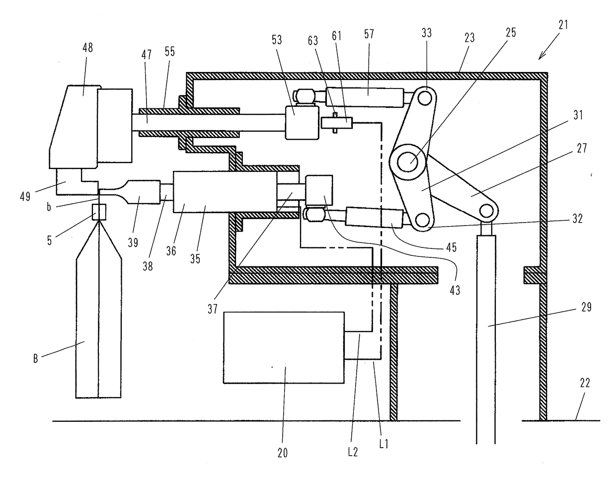
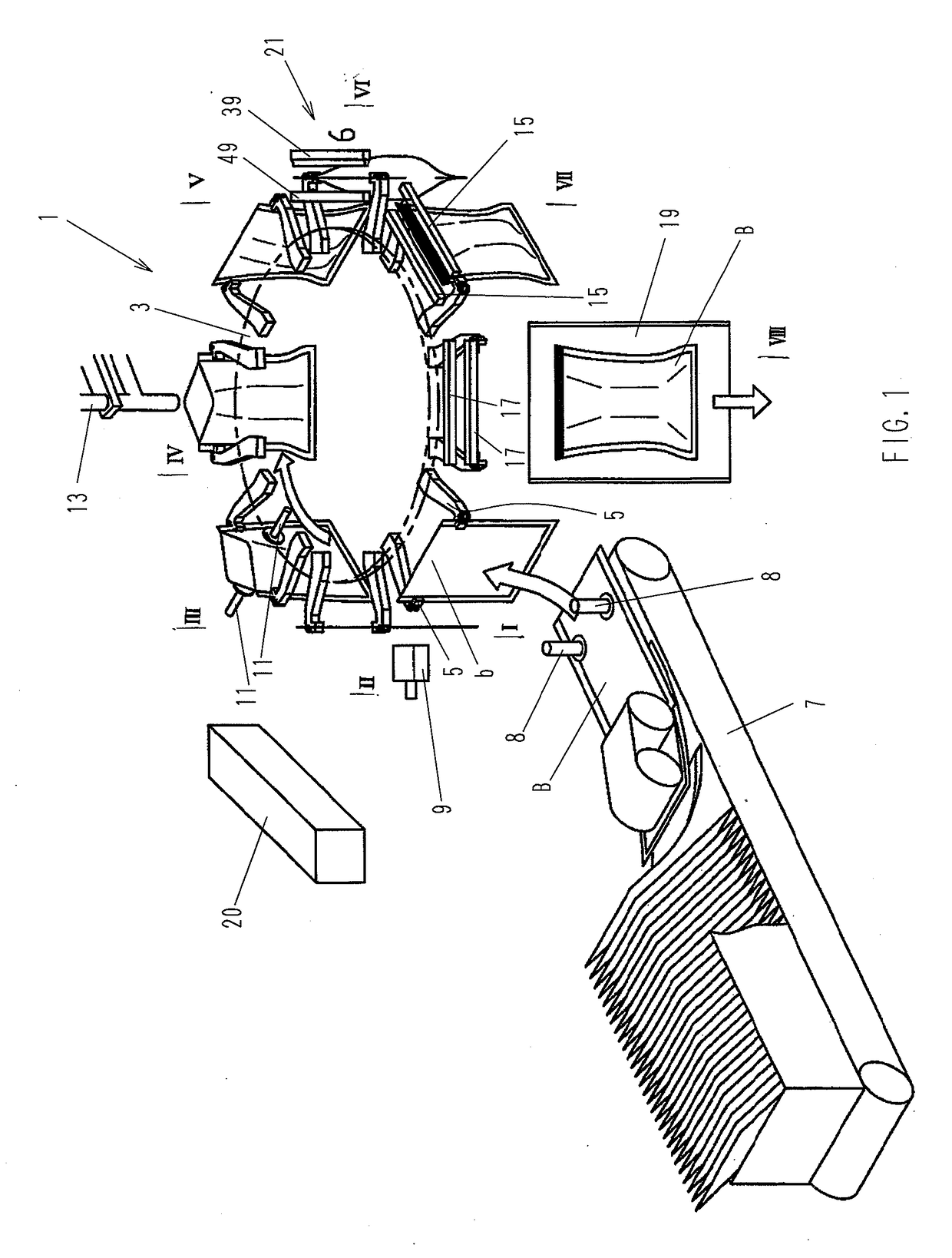
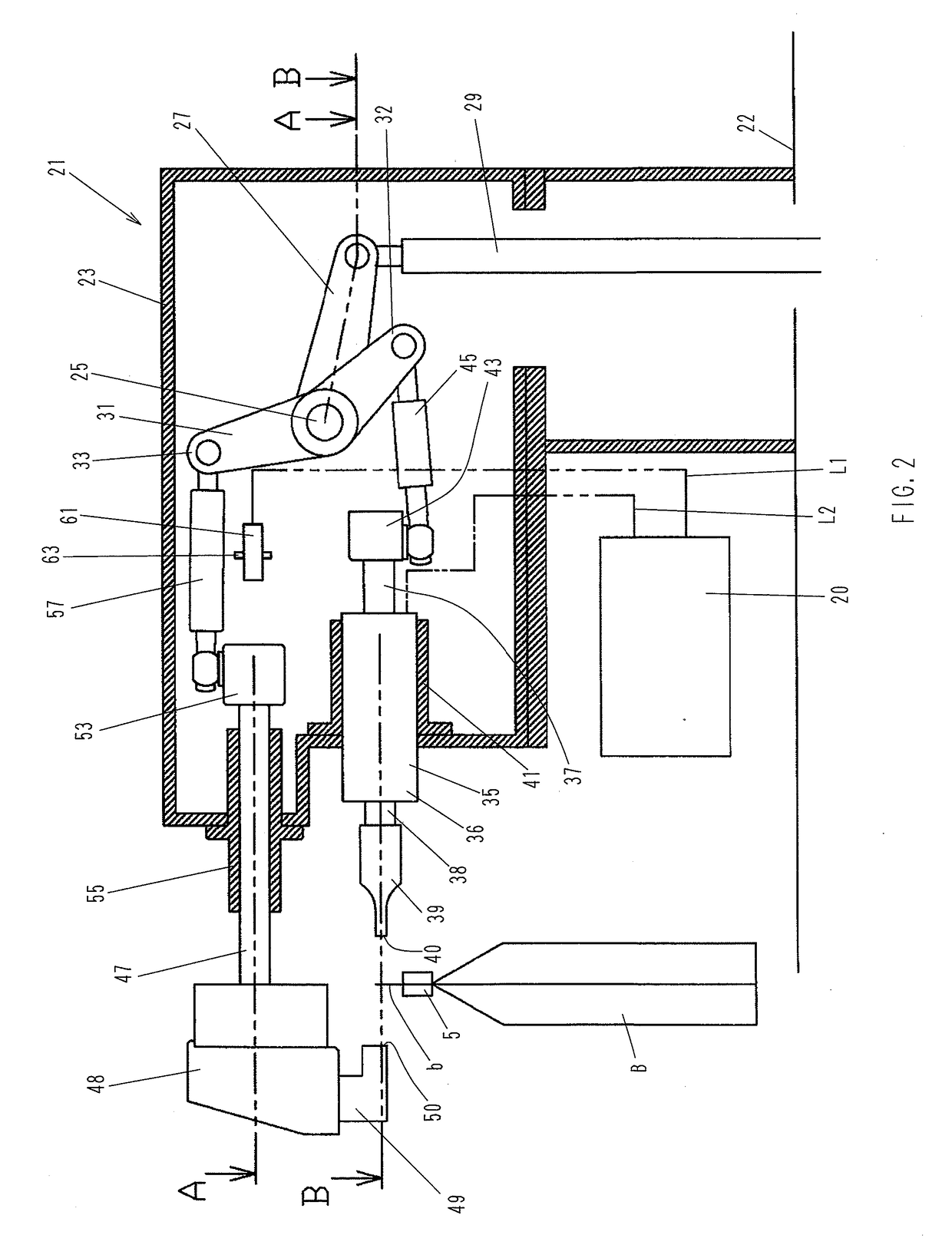
[0040]Next, the sealing apparatus 21 according to the present invention will be explained in detail with reference to FIGS. 2 to 6. FIG. 2 is a sectional side view showing the structure of the sealing apparatus 21, illustrating the sealing apparatus 21 when a bag B filled with a material to be packed at the previous step has moved to and stopped at the station VI. At this time, the sealing apparatus 21 has not yet been activated. FIGS. 3 and 4 are sectional views taken along the lines A-A and B-B, respectively, in FIG. 2.

[0041]It should be noted that, in the following embodiments of the present invention, the bag B is ultrasonically sealed along the edge of the bag mouth b. The reason for this is as follows. Ultrasonic sealing has the advantage of being capable of preventing biting of foreign matter, as has been stated above. However, if the bag B is ultrasonically sealed at a position away from the edge of the bag mouth b, the bag mouth b is open above the sealed portion; therefore...

third embodiment

[0058]FIG. 8 is a sectional side view of an ultrasonic sealing apparatus 75 showing the ultrasonic sealing apparatus 75 in standby position. FIG. 9 is a sectional view taken along the line C-C in FIG. 8. In the figures, reference numeral 76 denotes an anvil. The anvil 76 is secured through an insulator 79 to the lower side of an anvil support member 78 attached to the distal end of a sliding shaft 47 sliding through the guide 55 secured to the frame 23. The insulator 79 prevents formation of a closed circuit which would otherwise be formed between the anvil 76 and the horn 39 through the anvil support member 78, the sliding shaft 47, the guide 55, the frame 23, and the vibrator 35, or between the anvil 76 and the horn 39 through the anvil support member 78, the sliding shaft 47, the second connecting rod 57, the forked lever 31, the first connecting rod 45, and the vibrator 35, when the pressing surface 40 of the horn 39 and a pressing surface 77 of the anvil 76 directly contact ea...


PUM

PropertyMeasurementUnit
electric resistanceaaaaaaaaaa
inertia forceaaaaaaaaaa
distanceaaaaaaaaaa

Abstract

A horn and an anvil are moved toward and away from each other by axially reciprocating a driving rod and thereby reciprocatingly rotating a forked lever in a predetermined angle range. The horn and the anvil are moved toward and pressed against each other with a predetermined force with a bag mouth b held therebetween. A sensor detects the position of a second mounting block secured to the rear end of a sliding shaft of the anvil, thereby detecting the distance between respective pressing surfaces of the horn and the anvil, i.e. the thickness m of a portion of the bag mouth held between the pressing surfaces. When the thickness m is not less than a predetermined threshold value M, a vibrator is activated to perform sealing. When the thickness m is less than the threshold value M, no sealing is performed.

Description

RELATED APPLICATION DATA[0001]This application is a divisional of U.S. patent application Ser. No. 14 / 250,354 filed on Apr. 10, 2014, which is hereby incorporated by reference.BACKGROUND OF THE INVENTIONTechnical Field[0002]The present invention relates to a sealing apparatus for use in a bag filling and packaging machine in which a bag is held by being gripped at its laterally opposite side edges with a pair of laterally spaced grippers, and the bag held in this way is moved intermittently or continuously along a predetermined path to sequentially undergo predetermined packaging processes such as opening of the bag mouth, filling of an article to be packaged into the bag, and sealing of the bag mouth. More particularly, the present invention relates to an ultrasonic sealing apparatus using ultrasonic waves to perform sealing.Background Art[0003]An ultrasonic sealing apparatus using ultrasonic waves is known as a sealing apparatus for use in a bag filling and packaging machine. Ultr...

Claims


Application Information

Patent Timeline
Patent Type & Authority Applications(United States)
IPC IPC(8): B65B51/22B29C65/08B65B43/46B65B51/14B29C65/78B29C65/00B65B57/02B65B43/16B29L31/00
CPCB29C66/8242B29C66/8224B65B57/02B65B51/225B29C66/92311B29C66/9231B29C66/8746B29C66/849B29C66/83221B29C66/8225B29C66/43121B29C66/1122B29C65/7882B29C65/08B29L2031/7128B65B51/146B65B43/465B65B43/16B29C66/0062
Inventor YAMAMOTO, KAZUNORIHONDA, YASUYUKIYAMANE, NORIYUKI
Owner TOYO JIDOKI CO LTD
Why Eureka
Try Eureka