Assembly for adjusting an adjustment element relative to a stationary portion of a vehicle

a technology for adjusting elements and vehicles, applied in the direction of power supply, door/window fittings, constructions, etc., can solve problems such as large loads in operation

Active Publication Date: 2017-11-23
BROSE FAHRZEUGTEILE GMBH & CO KG
View PDF0 Cites 6 Cited by
  • Summary
  • Abstract
  • Description
  • Claims
  • Application Information

AI Technical Summary

Benefits of technology

[0023]In a development the coupling device can have a slipping, third condition, in which a first coupling element operatively connected with the drive motor and a second coupling element operatively connected with the transmission element slippingly cooperate. In this slipping, third condition of the coupling device the drive motor thus is coupled with the transmission element to a limited extent, wherein in this condition a braking force for example can be provided via the coupling device, in order to brake a manual adjustment of the adjustment element independent of the drive motor in a controlled way. For such braking effect the first coupling element for example can be retained via the drive motor, while the second coupling element, which is operatively connected with the transmission element, is moved when the transmission element is moved relative to the first coupling element and thereby slips at the first coupling element, so that the first coupling element and the second coupling element slippingly cooperate.
[0024]For this slipping, third condition of the coupling device the control device also can be formed to carry out a diagnosis. For example, the control device can be formed to actuate the drive motor for executing a third diagnostic routine, while the coupling device is in the slipping, third condition. In this way, for example, the braking effect of the coupling device can be measured, in order to calibrate the braking effect and to be able to adjust the same in a controlled way in the future operation. For determining the braking force the drive motor can be driven, wherein the motor current is measured, in order to determine the braking force provided by the coupling device in the slipping, third condition with reference to the motor current.
[0025]It also is conceivable and possible to effect cleaning of the (braking) coupling device by means of a third diagnostic routine by driving the drive motor in the slipping, third condition of the coupling device, in that the coupling elements of the coupling device are slippingly moved relative to each other.
[0026]Diagnostic routines as described above can be carried out in the manufacture or assembly of the adjustment element, e.g. of the vehicle door, hence in the production (e.g. as so-called end-of-line test as operability test after the manufacture). Such diagnostic routines can, however, also be carried out during operation after delivery of the vehicle to a customer. The diagnostic routines can be executed by the control device under completely automatic control, wherein an adaptation of system parameters and a calibration of the system can be performed automatically by the control device and error messages also can be generated and displayed automatically. By using such diagnostic and control routines ageing effects in the entire system of the adjustment element can be compensated and post-normalized, so that the operability of the adjustment system is obtained, possible malfunctions can be compensated or error messages can be generated, in order to provide for maintenance.

Problems solved by technology

In an adjustment system for example of a vehicle side door great loads occur in operation.

Method used


Image

  • Assembly for adjusting an adjustment element relative to a stationary portion of a vehicle
  • Assembly for adjusting an adjustment element relative to a stationary portion of a vehicle
  • Assembly for adjusting an adjustment element relative to a stationary portion of a vehicle

Examples


Embodiment Construction

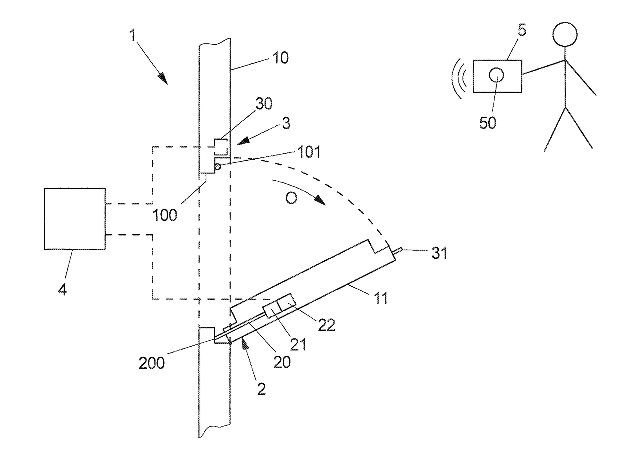
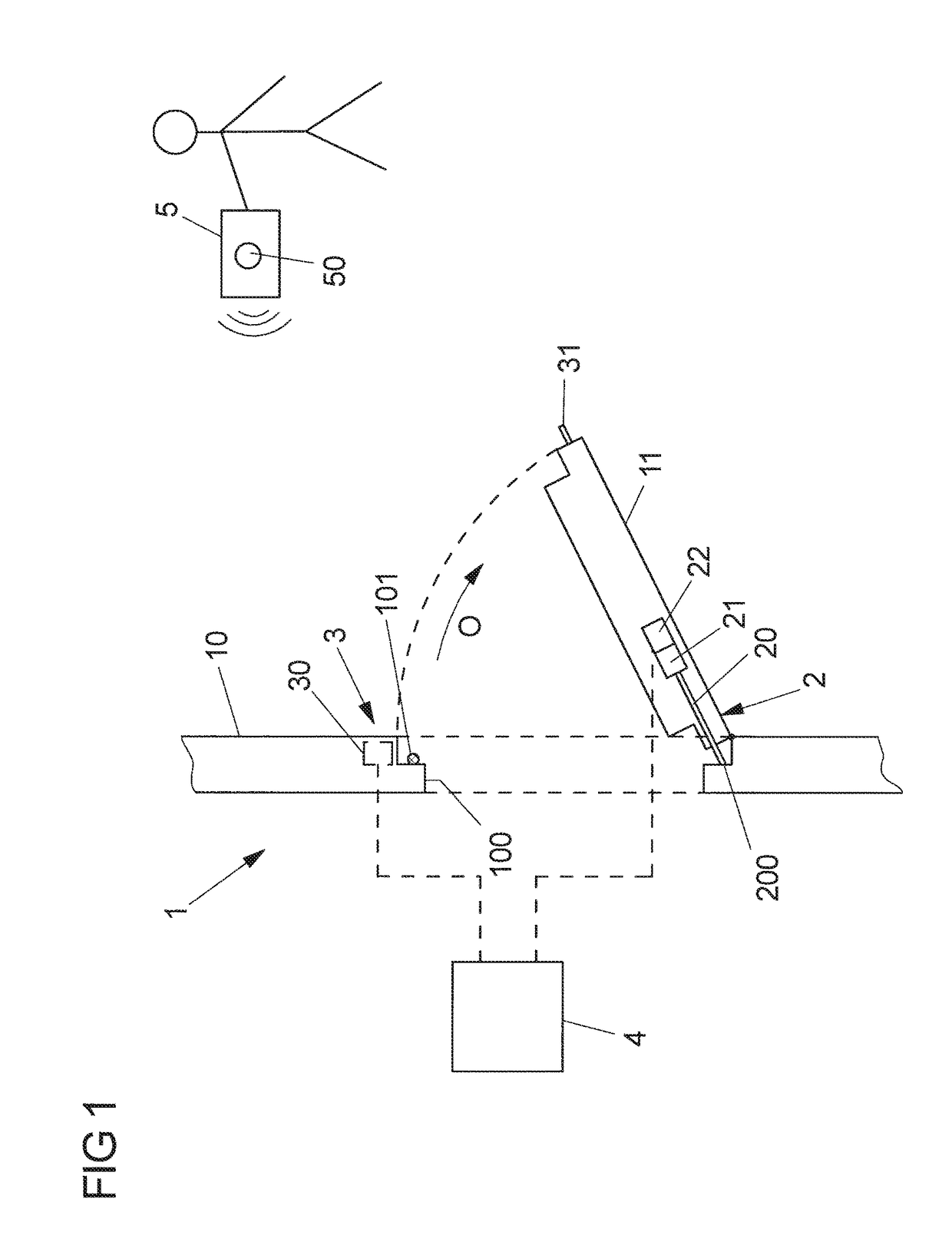
[0038]FIG. 1 shows a schematic view of a vehicle 1 which includes a vehicle body 10 and an adjustment element in the form of a vehicle door 11, which is pivotable on the vehicle body 10 about a pivot axis along an opening direction O.

[0039]The adjustment element 11 can be realized for example by a vehicle side door or also by a tailgate. In a closed position the adjustment element 11 covers a vehicle opening 100 in the vehicle body 10, for example a transverse opening or a tailgate opening in the vehicle body 10.

[0040]It should be noted that the adjustment element 11 for example can also be shiftably arranged on the vehicle body 10, for example as sliding door. What will be explained below analogously is also applicable to the adjustment element to be shifted.

[0041]By means of a driving device 2 the adjustment element 11 is electromotively movable from its closed position into an open position, so that the adjustment element 11 in the form of the vehicle door can be moved automatica...


PUM


Abstract

An assembly for adjusting an adjustment element relative to a stationary portion of a vehicle, in particular of a vehicle door relative to a vehicle body comprises a drive motor for electromotively adjusting the adjustment element and an electrically actuatable locking device for locking the adjustment element with the stationary portion of the vehicle in a closed position, wherein the locking device has a locked condition in which the locking device is locked relative to the stationary portion for blocking the adjustment element in the closed position, and an unlocked condition in which the locking device is unlocked for adjusting the adjustment element relative to the stationary portion. A control device serves for controlling the drive motor and the locking device. It is provided that the control device is formed to actuate the drive motor for executing a diagnostic routine, while the locking device is in the locked condition.

Description

REFERENCE TO RELATED APPLICATION[0001]This application claims priority to German Patent Application No. 10 2016 208 438.0 filed on May 17, 2016, the entirety of which is incorporated by reference herein.BACKGROUND[0002]The invention relates to an assembly for adjusting an adjustment element relative to a stationary portion of a vehicle and to a method for adjusting an adjustment element relative to a stationary portion of a vehicle.[0003]Such adjustment element for example can be realized by a vehicle door, for example a vehicle side door or a tailgate of a vehicle. Such vehicle door can be moved relative to a vehicle body, in order to clear a vehicle opening. The vehicle door for example can be pivotally arranged on the vehicle body. It likewise is conceivable and possible, however, that the vehicle door is shiftably arranged on the vehicle body.[0004]Such assembly comprises a drive motor for electromotively adjusting the adjustment element. In a closed position the adjustment elem...

Claims


Application Information

Patent Timeline
Patent Type & Authority Applications(United States)
IPC IPC(8): E05F15/40E05F15/60E05B81/04E05B81/64
CPCE05F15/40E05B81/64E05B81/04E05F15/60E05F15/611E05Y2201/216E05Y2400/10E05Y2400/50E05Y2400/502E05Y2800/404E05Y2800/43E05F15/619E05F15/622
Inventor HERRMANN, CHRISTIANUEBEL, WOLFGANG
Owner BROSE FAHRZEUGTEILE GMBH & CO KG
Why Eureka
Try Eureka