Gear Pump

a gear pump and gear technology, applied in the direction of machines/engines, rotary/oscillating piston pump components, liquid fuel engines, etc., can solve problems such as unstable pump performance, and achieve the effect of stabilizing pump performance and suppressing fluid from leaking

Inactive Publication Date: 2017-11-23
JTEKT CORP
View PDF0 Cites 1 Cited by
  • Summary
  • Abstract
  • Description
  • Claims
  • Application Information

AI Technical Summary

Benefits of technology

[0008]When the gear pump according to the above aspect is viewed in the axial direction of the support shafts during rotation of the gears, the first contact point of each gear (addendum circle) with respect to the inner peripheral surface that defines the housing hole is covered with the side plates and sealed. Thus, it is possible to suppress the fluid from leaking from the high pressure-side to the low pressure-side while bypassing the first contact points, at an axial end portion of each of the gears. Thus, it is possible to deliver stable pump performance. In the above aspect, each first contact point is a contact point at which the addendum circle is in contact with the inner peripheral surface via a fluid film, such as a thin oil film.

Problems solved by technology

This makes the pump performance unstable.

Method used


Image

  • Gear Pump
  • Gear Pump
  • Gear Pump

Examples


Embodiment Construction

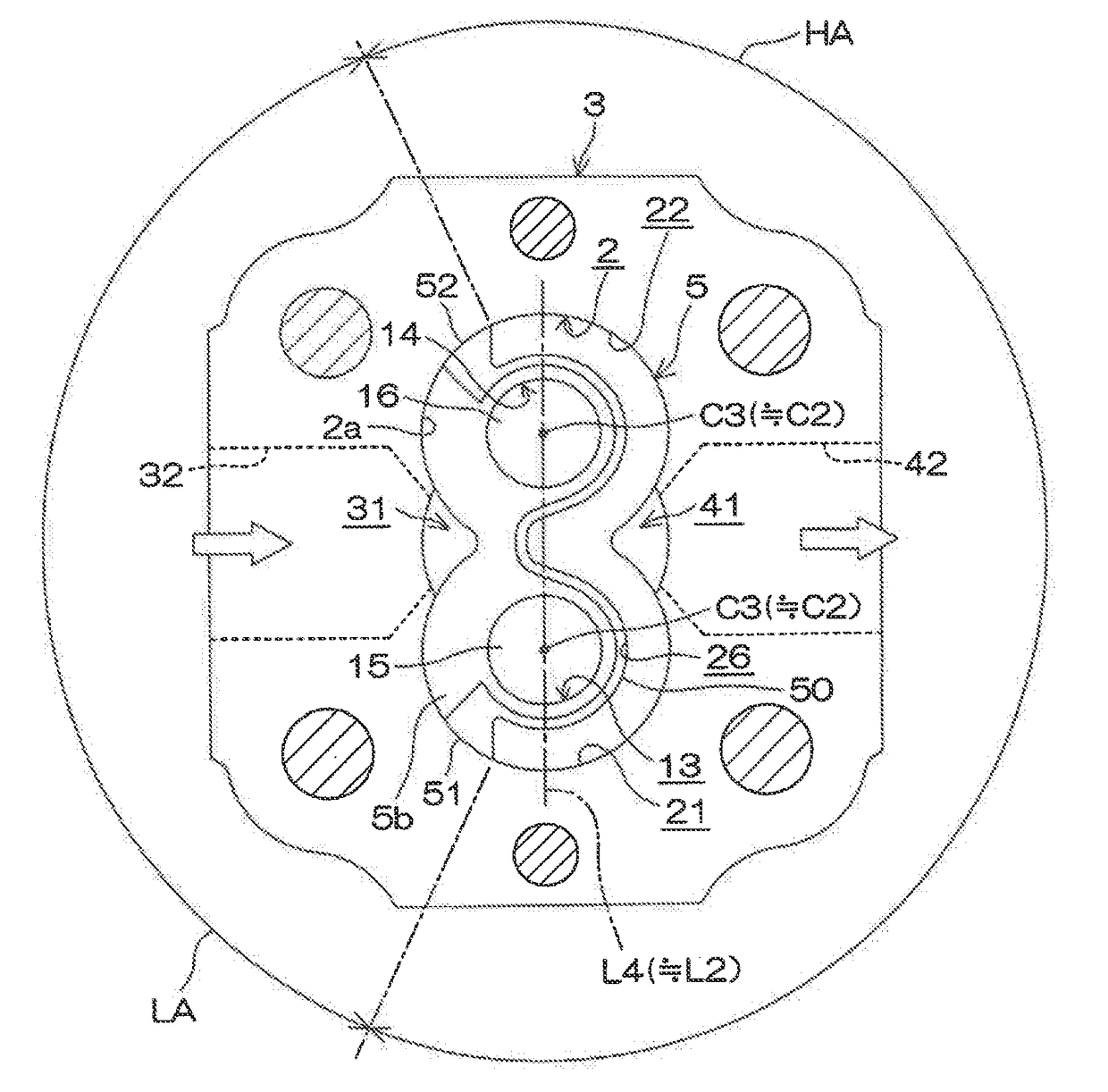
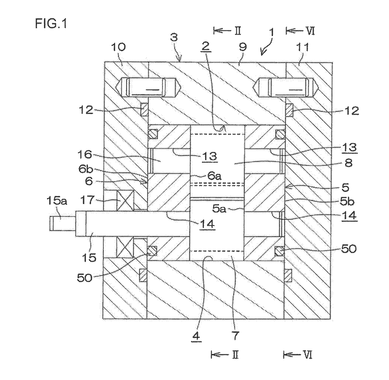
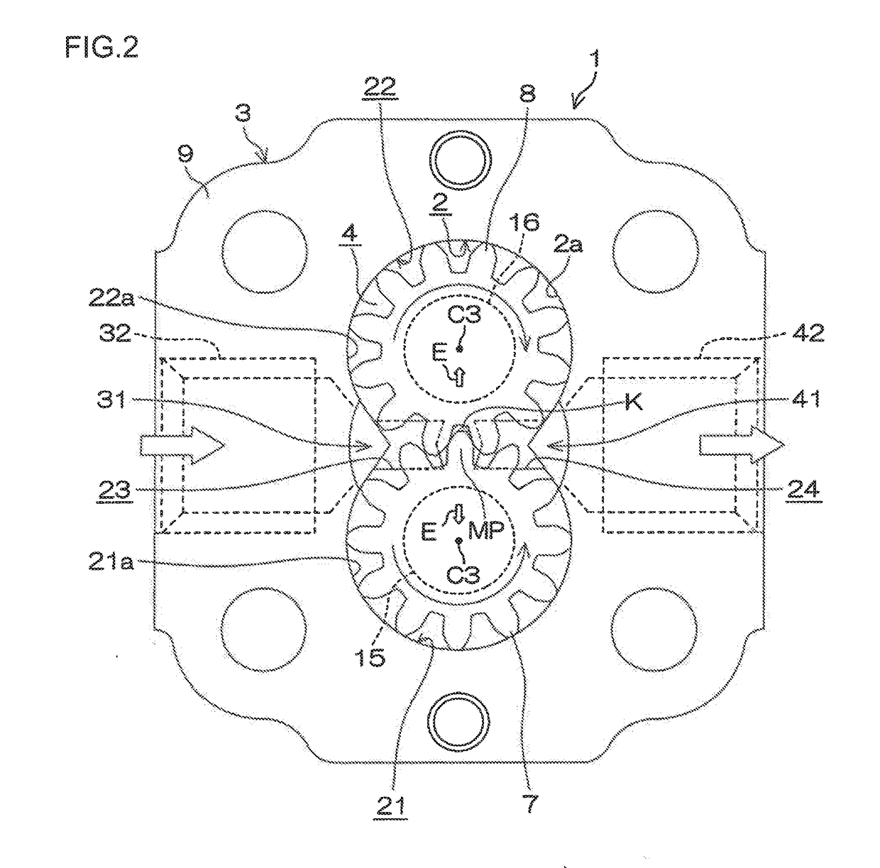
[0023]Example embodiments of the invention will be described with reference to the accompanying drawings. FIG. 1 is a front sectional view of a gear pump according to an embodiment of the invention. FIG. 2 is a sectional view taken along line II-II in FIG. 1, in which hatching representing sections is omitted. As illustrated in FIG. 1 and FIG. 2, a gear pump 1 includes a housing 3, a pair of side plates 5, 6, and a pair of a drive gear 7 and a driven gear 8. The housing 3 has a housing hole 2. The side plates 5, 6 are disposed in the housing hole 2 so as to face each other. The side plates 5, 6 are disposed apart from each other such that a gear chamber 4 is defined therebetween. The drive gear 7 and the driven gear 8 are disposed in the gear chamber 4 so as to be meshed with each other.

[0024]The housing 3 includes a tubular main body 9 and a pair of cover plates 10, 11. The cover plates 10, 11 are screwed to the tubular main body 9 so as to cover both axial end surfaces of the tubu...


PUM


Abstract

In a gear pump, a gear chamber is defined in a housing hole of a housing. A pair of gears is housed in the gear chamber. The gears are rotatably supported at support holes of a pair of side plates via support shafts. As viewed in an axial direction of the support shafts during rotation of the gears, addendum circles of the gears displaced under a differential pressure between a low-pressure chamber and a high-pressure chamber form first contact points with respect to an inner peripheral surface that defines a housing hole. As viewed in the axial direction of the support shafts during rotation of the gears, the first contact points are covered with the side plates displaced under the differential pressure.

Description

INCORPORATION BY REFERENCE[0001]The disclosure of Japanese Patent Application No. 2016-100851 filed on May 19, 2016 including the specification, drawings and abstract, is incorporated herein by reference in its entirety.BACKGROUND OF THE INVENTION1. Field of the Invention[0002]The invention relates to a gear pump.2. Description of the Related Art[0003]A commonly-used gear pump has a structure in which a pair of gears meshed with each other is housed in a housing, a gear chamber is defined in a housing hole by a pair of side plates disposed with the gears interposed therebetween in an axial direction, and support shafts of the gears are rotatably supported at support holes provided in the side plates. Refer to, for example, Japanese Patent Application Publication No. H10-122160 (JP H10-122160 A). When the gear pump is viewed in the axial direction of the gears, a low-pressure chamber and a high-pressure chamber are arranged inside the gear chamber, with a meshing position (i.e., a po...

Claims


Application Information

Patent Timeline
Patent Type & Authority Applications(United States)
IPC IPC(8): F04C15/00F04C18/14F04C29/12F04C2/14F04C29/00F04C15/06
CPCF04C15/0049F04C2/14F04C15/06F04C2240/60F04C29/0035F04C29/12F04C2240/30F04C18/14F04C2/18F04C15/0046F04C2240/50
Inventor YOSHIDA, NAOHITO
Owner JTEKT CORP
Why Eureka
Try Eureka