
Gas analysis apparatus

Inactive Publication Date: 2017-11-23
HORIBA LTD
View PDF4 Cites 2 Cited by
  • Summary
  • Abstract
  • Description
  • Claims
  • Application Information

AI Technical Summary

Benefits of technology

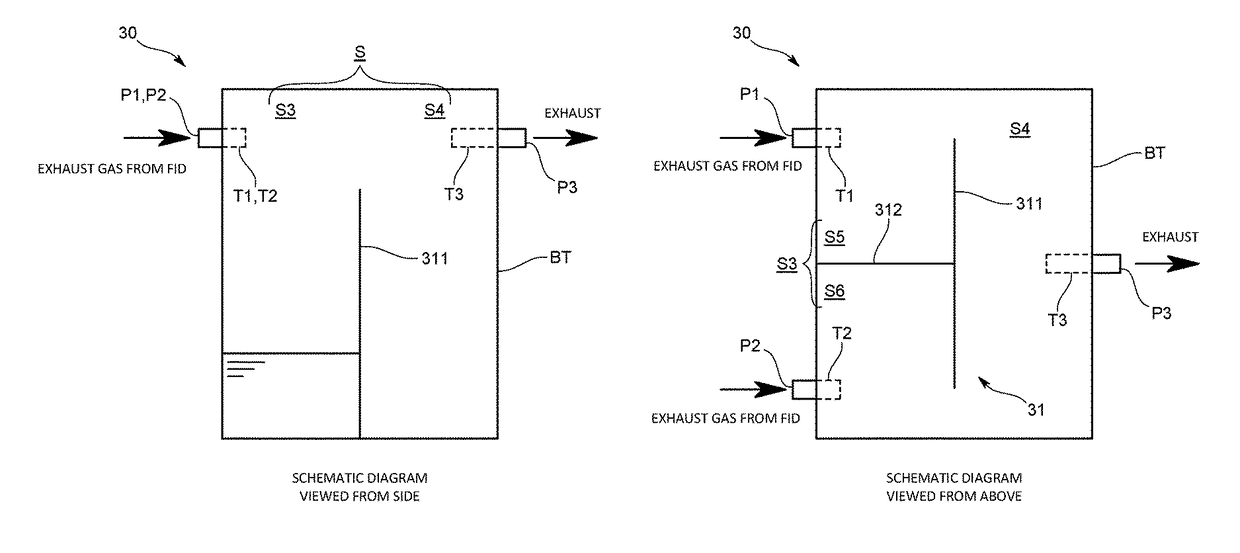
The present invention allows for a smaller exhaust gas analysis apparatus with FIDs that can be sure ignited.

Problems solved by technology

With the above configuration, however, the following problem can occur.
Even with the use of a sequence of concurrently igniting the FIDs, it is difficult to obtain a state in which all of the FIDs are kept burning in the above configuration.

Method used


Image

  • Gas analysis apparatus
  • Gas analysis apparatus
  • Gas analysis apparatus

Examples


Embodiment Construction

[0032]One embodiment of a gas analysis apparatus according to the present invention is described below with reference to the drawings.

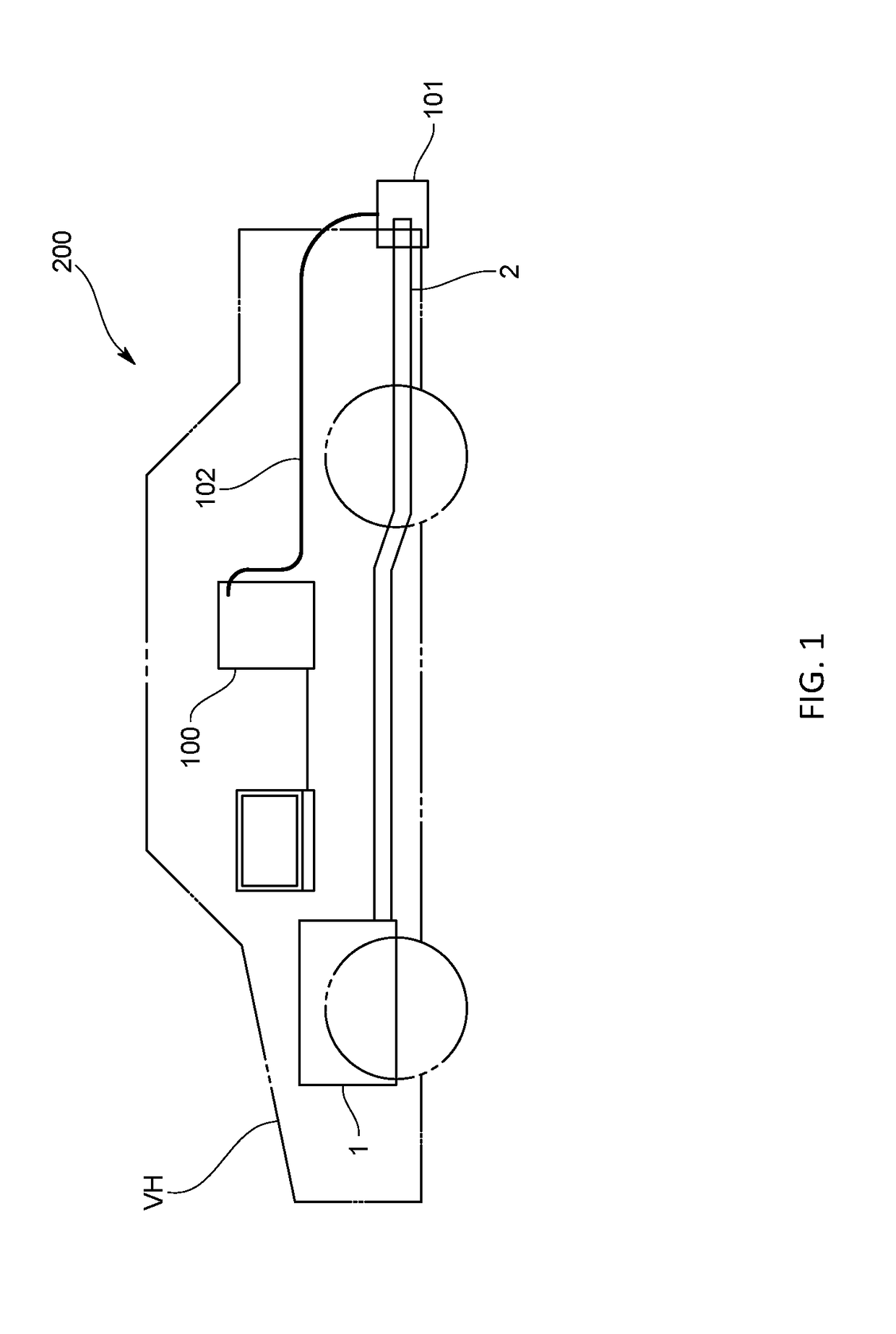
[0033]As shown in FIG. 1, the gas analysis apparatus 100 of the present embodiment is an on-vehicle type to be mounted on a vehicle VH (hereinafter also referred to as “an exhaust gas analysis apparatus 100”). The gas analysis apparatus 100 constitutes an exhaust gas analysis system 200 together with an exhaust gas collection mechanism 101 and a heated tube unit (hot hose) 102. The gas analysis apparatus 100 is one of various exhaust gas analysis apparatuses to analyze carbon monoxide (CO), carbon dioxide (CO2), nitrogen oxide (NOx), and hydrocarbon (HC), which are contained in exhaust gas.

[0034]The exhaust gas analysis system 200 is briefly described below. All or part of exhaust gas is configured to be collected by the exhaust gas collection mechanism 101 attached to an opening-side end of an exhaust pipe 2 being coupled to an internal combustion en...


PUM


Abstract

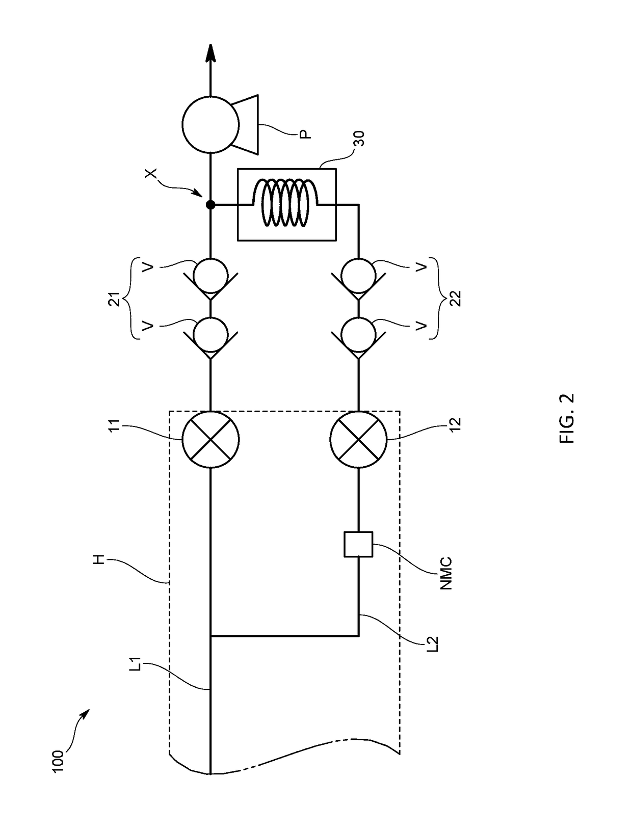
In a gas analysis apparatus including analyzers that need ignition, such as FIDs, in order to make it possible to surely ignite the analyzers while downsizing the entire apparatus, the apparatus includes first and second analyzers to accept a sample gas, a first gas line provided with the first analyzer, a second gas line provided with the second analyzer and joined downstream of the first analyzer in the first gas line. At least one of the first analyzer and the second analyzer is configured to cause pressure fluctuations in the gas line including the analyzer when analyzing the sample gas. A first backflow prevention mechanism is disposed between another of the analyzers and a junction of the gas lines. The first backflow prevention mechanism is configured to prevent a fluid from flowing backward from the one of the analyzers through the junction toward the another of the analyzers.

Description

BACKGROUND OF THE INVENTIONField of the Invention[0001]The present invention relates to a gas analysis apparatus to analyze, for example, exhaust gas.Background Art[0002]As an exhaust gas analysis apparatus, there has conventionally been one which includes a first flame ionization detector (hereinafter referred to as “a first FID”) to accept exhaust gas and a second flame ionization detector (hereinafter referred to as “a second FID”) to accept the exhaust gas, a first exhaust gas line provided with the first FID, and a second exhaust gas line provided with the second FID, as described in Patent Document 1.[0003]The exhaust gas analysis apparatus includes a filter device disposed only upstream of the second FID in the second exhaust line, and is configured to calculate concentrations of various ingredients and a PM concentration on the basis of a difference between output values of the first FID and the second FID.[0004]Meanwhile, when the exhaust gas analysis apparatus provided wit...

Claims


Application Information

Patent Timeline
IPC IPC(8): G01N33/00G01N21/72G01N21/03G01N35/10G01N27/62F16K15/00
CPCG01N33/0036G01N21/03F16K15/00G01N27/626G01N35/1097G01N21/72G01N33/0024
Inventor FUKAMI, SHUNMOHARA, HARUHISAAOKI, SHINTARO
Owner HORIBA LTD
Learn More