Pulse plating of lithium material in electrochemical devices

a lithium material and electrochemical device technology, applied in the direction of cell components, final product manufacturing, sustainable manufacturing/processing, etc., can solve the problems of insufficient structure of existing anode materials and other problems

Active Publication Date: 2017-11-23
QUANTUMSCAPE CORP
View PDF3 Cites 18 Cited by
  • Summary
  • Abstract
  • Description
  • Claims
  • Application Information

AI Technical Summary

Problems solved by technology

Unfortunately, existing anode materials and structures thereof are often inadequate.

Method used


Image

  • Pulse plating of lithium material in electrochemical devices
  • Pulse plating of lithium material in electrochemical devices
  • Pulse plating of lithium material in electrochemical devices

Examples


Embodiment Construction

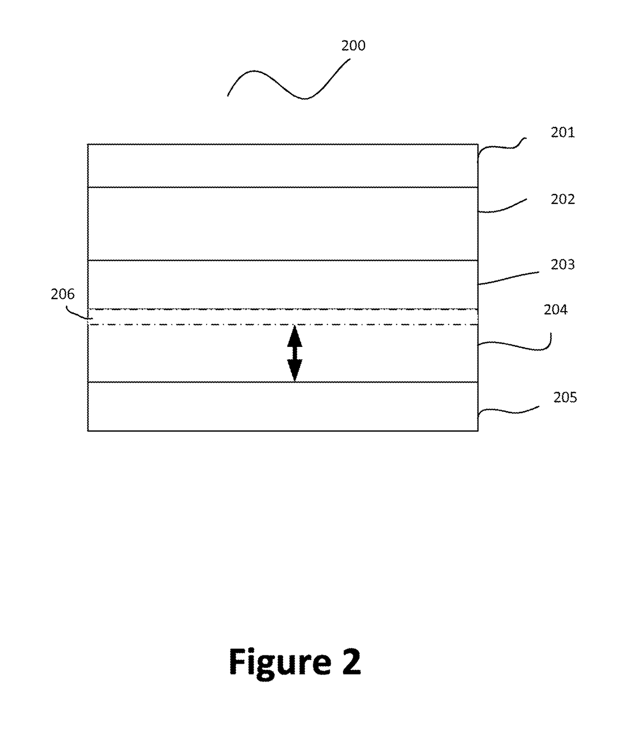
[0013]The present invention is directed to battery system and operation thereof. In an embodiment, lithium material is plated onto the anode region of a lithium secondary battery cell by a pulsed current. The pulse current may have both positive and negative polarity. One of the polarities causes lithium material to plate onto the anode region, and the opposite polarity causes lithium dendrites to be removed. There are other embodiments as well.

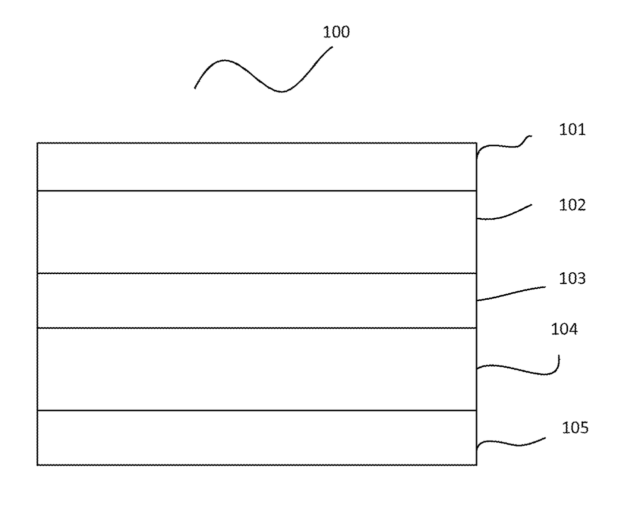
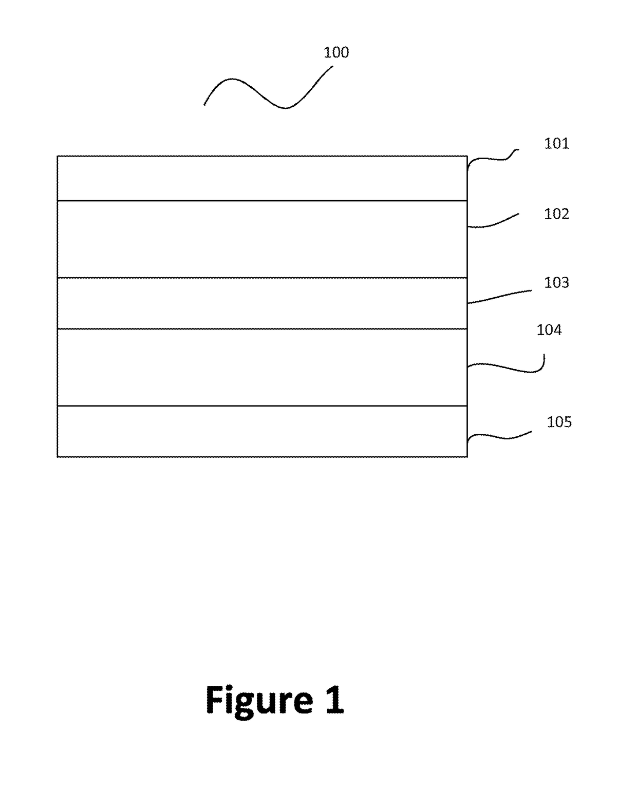
[0014]As described above, lithium ions move through electrolyte and between positive and negative electrodes upon charging and discharging process. Typically, the anode region of a lithium battery cell comprises material such as graphite to store lithium ions when the battery is charged. According to embodiments of the present invention, lithium ions are plated onto the current collector at the side of the negative electrode. FIG. 1 is a simplified diagram illustrating a battery cell having a lithiated anode according to an embodiment of the ...


PUM

PropertyMeasurementUnit
ionic conductivityaaaaaaaaaa
pulse currentaaaaaaaaaa

Abstract

The present invention is directed to battery system and operation thereof. In an embodiment, lithium material is plated onto the anode region of a lithium secondary battery cell by a pulsed current. The pulse current may have both positive and negative polarity. One of the polarities causes lithium material to plate onto the anode region, and the opposite polarity causes lithium dendrites to be removed. There are other embodiments as well.

Description

CROSS-REFERENCES TO RELATED APPLICATIONS[0001]This application claims priority to U.S. Provisional Patent Application No. 61 / 839,339, filed Jun. 25, 2013, entitled “PULSE PLATING OF LITHIUM MATERIAL IN ELECTROCHEMICAL DEVICES”, which is incorporated by reference herein for all purposes.STATEMENT AS TO RIGHTS TO INVENTIONS MADE UNDER FEDERALLY SPONSORED RESEARCH AND DEVELOPMENT[0002]Not ApplicableREFERENCE TO A “SEQUENCE LISTING,” A TABLE, OR A COMPUTER PROGRAM LISTING APPENDIX SUBMITTED ON A COMPACT DISK[0003]Not ApplicableBACKGROUND OF THE INVENTION[0004]The present invention is directed to battery system and operation thereof.[0005]In the recent years, with a shortage of fossil-fuel based energy resources and adverse environmental effects from the consumption of fossil fuels, both the public and private sectors have made substantial investments into developing clean technologies. An important aspect of clean technologies is energy storage, or simply battery systems. In the past, m...

Claims


Application Information

Patent Timeline
Patent Type & Authority Applications(United States)
IPC IPC(8): H01M4/04H01M10/0585H01M10/052
CPCH01M10/052H01M10/0585H01M4/045C25D5/18H01M4/1395C25D3/00Y02E60/10Y02P70/50C25D5/611Y02T10/70
Inventor HOLME, TIMOTHYMAYER, MARIELOVENESS, GHYRNCHEN, ZHEBOFASCHING, RAINER
Owner QUANTUMSCAPE CORP
Why Eureka
Try Eureka