
Electrophotographic photoconductor, image forming apparatus, and process cartridge

a photoconductor and electrostatic load technology, applied in the direction of electrographic process apparatus, instruments, optics, etc., can solve the problems of reduced chargeability due to electrostatic load, and gradual deterioration of electrical properties,

Inactive Publication Date: 2017-11-30
RICOH KK
View PDF3 Cites 2 Cited by
  • Summary
  • Abstract
  • Description
  • Claims
  • Application Information

AI Technical Summary

Benefits of technology

The present invention relates to an improved electrophotographic photoconductor that includes a support, an undercoat layer, and a photoconductive layer. The undercoat layer comprises zinc oxide particles, a urethane bond-containing resin, and methylethyl ketone oxime. The methylethyl ketone oxime content of the undercoat layer is controlled to follow a certain formula. This arrangement of layers provides improved performance and stability of the electrophotographic photoconductor.

Problems solved by technology

When the electrophotographic photoconductor is used over a long period, deteriorations in electrical properties, such as reduction in chargeability due to electrostatic load, gradually occur because a charging step and a charge-eliminating step are repeatedly performed on the electrophotographic photoconductor.
It has been known that deteriorations of the electrical properties largely influence image quality of output images, leading to serious problems, such as low image density, occurrences of background fog (may be also referred to as background deposition, fogging, or black spots, hereinafter), and low uniformity of images when continuously output.
However, the proposed electrophotographic photoconductor cannot maintain stable electrical properties and image quality when used over a long period.

Method used


Image

  • Electrophotographic photoconductor, image forming apparatus, and process cartridge
  • Electrophotographic photoconductor, image forming apparatus, and process cartridge
  • Electrophotographic photoconductor, image forming apparatus, and process cartridge

Examples


first embodiment

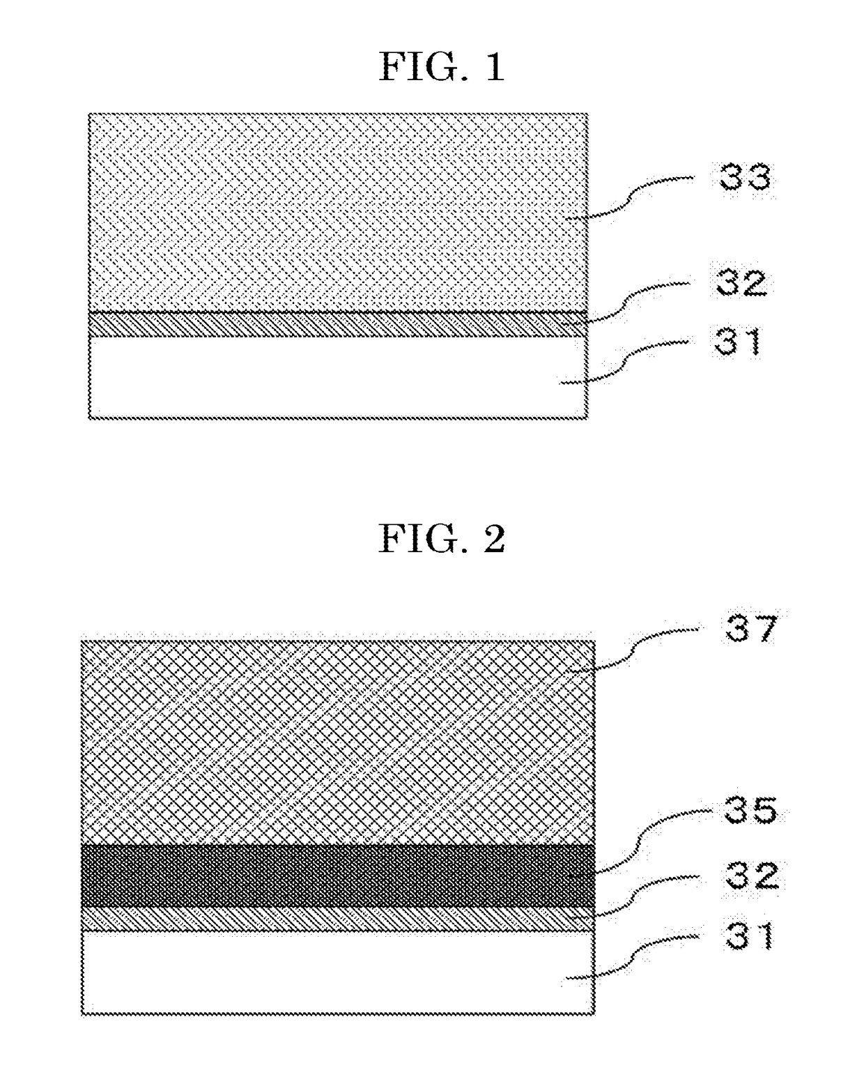
[0149]A layer configuration of the electrophotographic photoconductor according to a first embodiment will be described with reference to FIG. 1.

[0150]FIG. 1 illustrates a layer configuration including a single-layer photoconductive layer, and illustrates a layer configuration of the electrophotographic photoconductor where an undercoat layer 32 and a single-layer photoconductive layer 33 are sequentially disposed on a support 31.

second embodiment

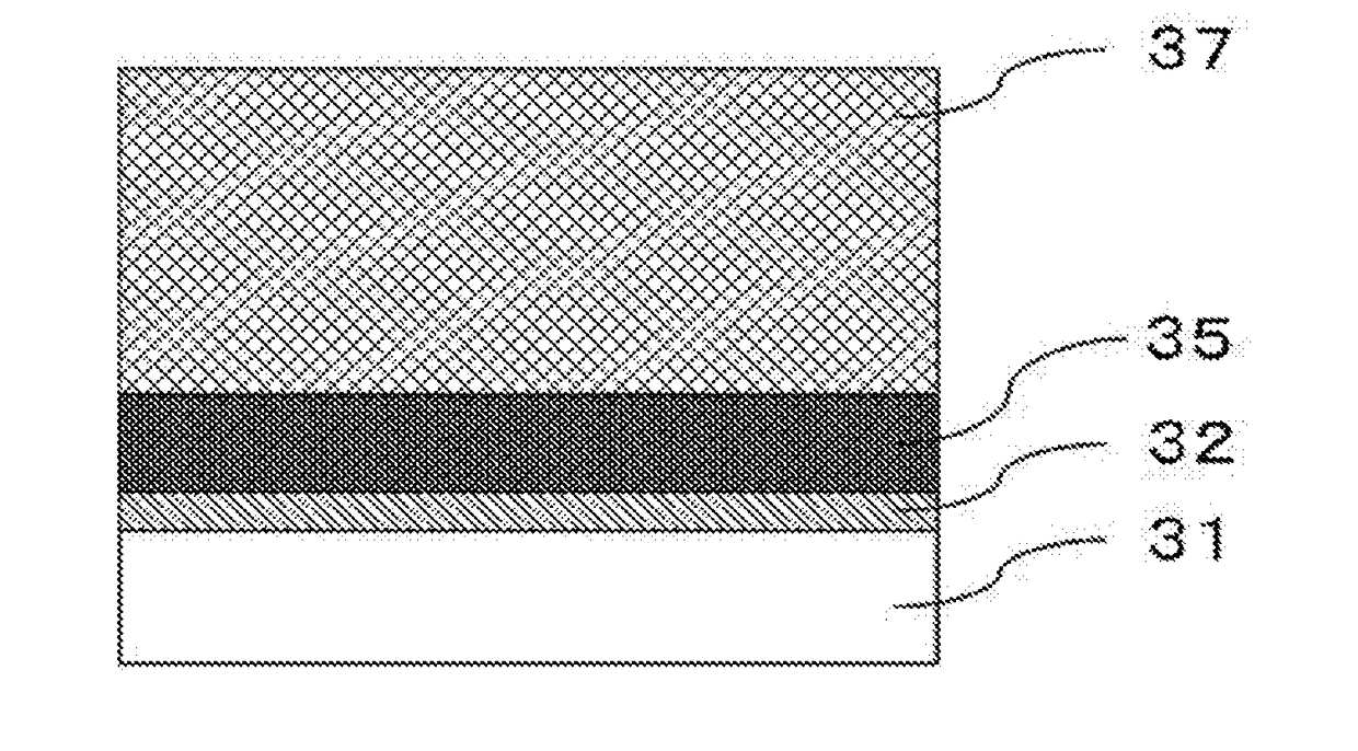
[0151]A layer configuration of the electrophotographic photoconductor according to a second embodiment will be described with reference to FIG. 2.

[0152]FIG. 2 illustrates a layer configuration including a laminate photoconductive layer, and illustrates a layer configuration of the electrophotographic photoconductor where an undercoat layer 32, a charge-generating layer 35, and a charge-transporting layer 37 are sequentially disposed on a support 31. Note that, a combination of the charge-generating layer 35 and the charge-transporting layer 37 corresponds to a photoconductive layer.

third embodiment

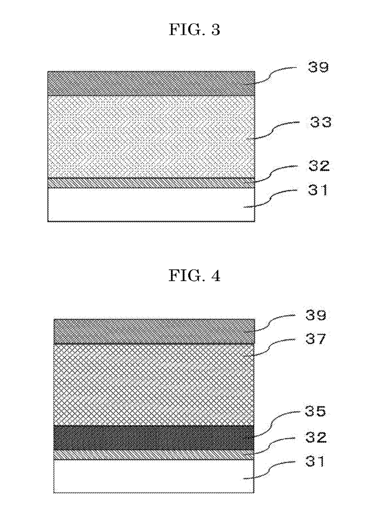
[0153]A layer configuration of the electrophotographic photoconductor according to a third embodiment will be described with reference to FIG. 3.

[0154]FIG. 3 illustrates a layer configuration including a single-layer photoconductive layer, and illustrate a layer configuration of the electrophotographic photoconductor where an undercoat layer 32, a photoconductive layer 33, and a protective layer 39 are sequentially disposed on a support 31.


PUM


Abstract

An electrophotographic photoconductor including a support, an undercoat layer, and a photoconductive layer, the undercoat layer and the photoconductive layer being disposed on the support in an order mentioned, wherein the undercoat layer includes zinc oxide particles, a urethane bond-containing resin, and methylethyl ketone oxime, and the undercoat layer satisfies a formula below:10<M / L<400  (Formula)where M is a ratio (ppm) of the methylethyl ketone oxime included in the undercoat layer, and L is an average thickness (μm) of the undercoat layer.

Description

CROSS-REFERENCE TO RELATED APPLICATIONS[0001]The present application claims priority under 35 U.S.C. §119 to Japanese Patent Application No. 2016-104684 filed May 25, 2016. The contents of which are incorporated herein by reference in their entirety.BACKGROUND OF THE INVENTIONField of the Invention[0002]The present disclosure relates to an electrophotographic photoconductor, and an image forming apparatus and a process cartridge both using the electrophotographic photoconductor.Description of the Related Art[0003]In an image forming method using an image forming apparatus, an image is formed by performing steps, such as a charging step, an exposure step, a developing step, a transfer step, and a charge-eliminating step, on an electrophotographic photoconductor (may be referred to as a “photoconductor” hereinafter). The electrophotographic photoconductor typically has a structure including a support, an undercoat layer formed on the support, and a photoconductive layer disposed on th...

Claims


Application Information

Patent Timeline
IPC IPC(8): G03G5/14G03G15/00
CPCG03G15/75G03G5/144
Inventor ISHIDA, TOSHIHIROSUZUKI, TETSUROKURIMOTO, EIJIASANO, TOMOHARUNII, DAISUKE
Owner RICOH KK
Learn More