
Multi-Layer PZT Microactuator Having A Poled But Inactive PZT Constraining Layer

a microactuator and constraining layer technology, applied in the direction of magnetic recording, data recording, instruments, etc., can solve problems such as stroke length loss

Active Publication Date: 2017-11-30
MAGNECOMP
View PDF18 Cites 6 Cited by
  • Summary
  • Abstract
  • Description
  • Claims
  • Application Information

AI Technical Summary

Benefits of technology

The use of constraining layers enhances stroke sensitivity, reduces sway and torsion mode gains, and increases the reliability of PZT microactuators by preventing cracking, leading to improved head positioning control and data storage capacity within a given volume.

Problems solved by technology

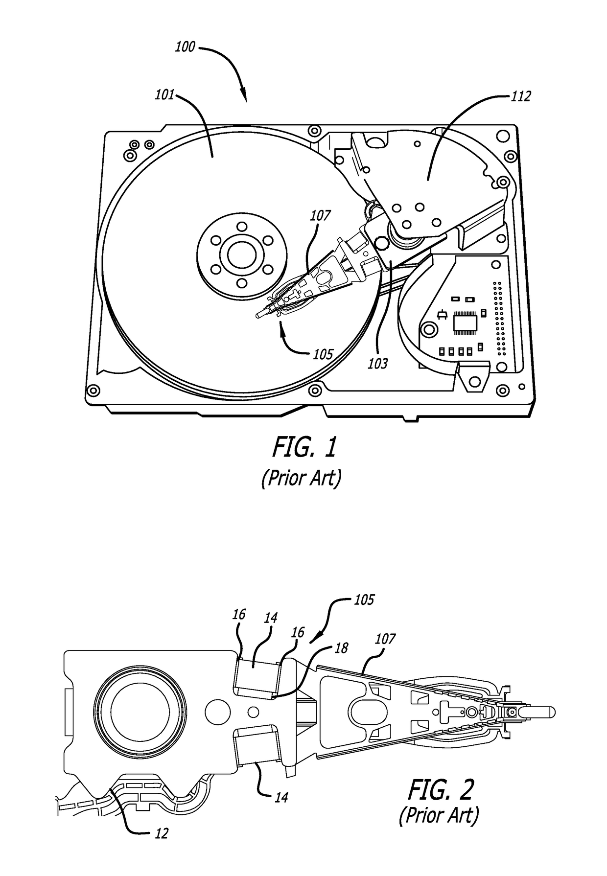
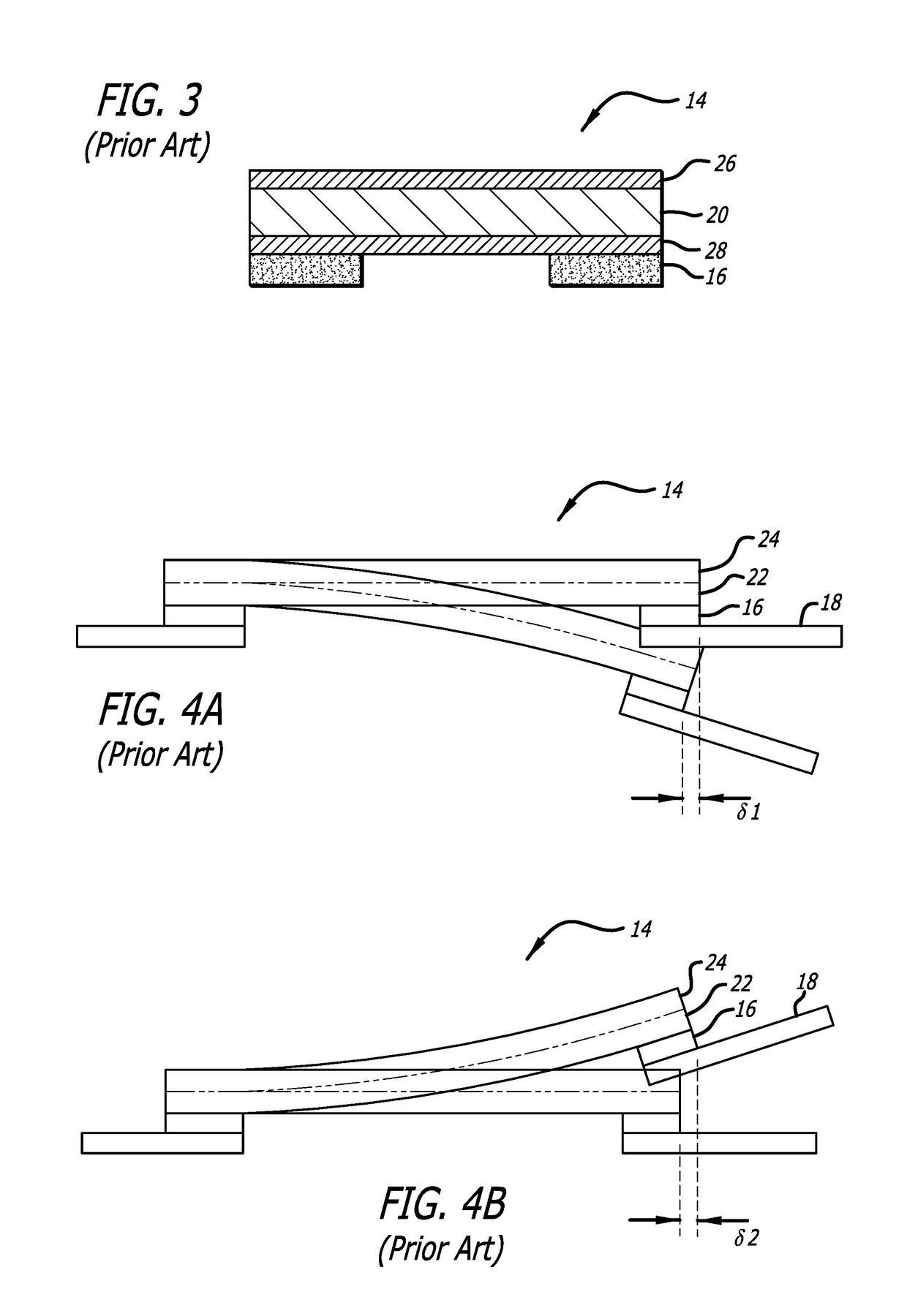
Thus, although purely linear expansion and contraction of the PZT upon actuation is desired, in the conventional mounting the PZT experiences bending either up or down which results in lost stroke length.

Method used


Image

  • Multi-Layer PZT Microactuator Having A Poled But Inactive PZT Constraining Layer
  • Multi-Layer PZT Microactuator Having A Poled But Inactive PZT Constraining Layer
  • Multi-Layer PZT Microactuator Having A Poled But Inactive PZT Constraining Layer

Examples


Embodiment Construction

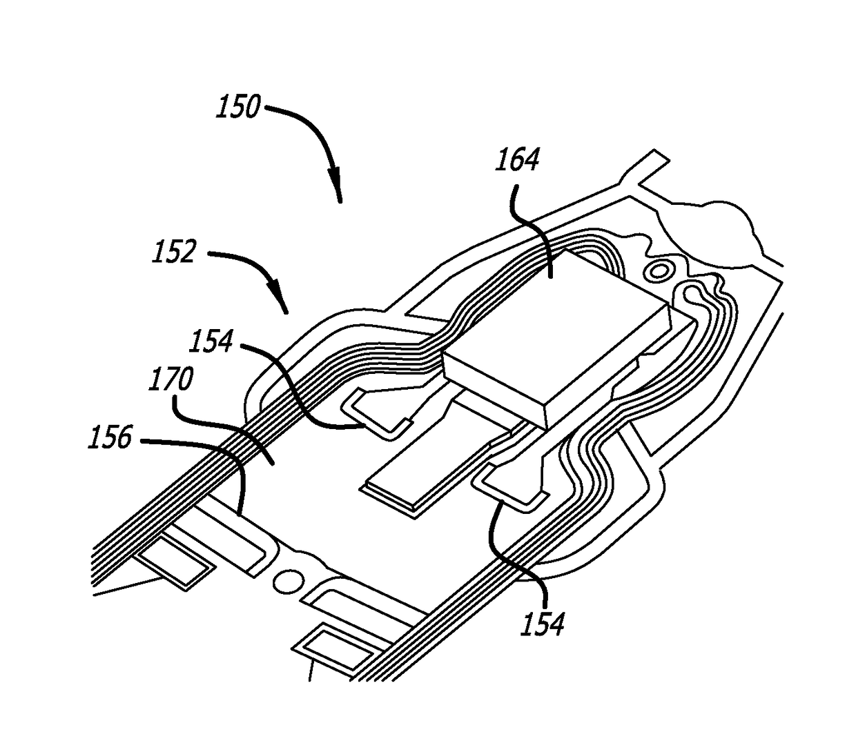
[0073]FIG. 7 is a side sectional view of a PZT microactuator assembly 114 having a constraining layer 130 bonded thereto in accordance with an embodiment of present invention. In keeping with the orientation shown in the figure, the side of the PZT which is bonded to the suspension will be referred to as the bottom side 129 of PZT 114, and the side of the PZT away from the side at which the PZT is bonded to the suspension will be referred to as the top side 127. According to the invention, one or more constraining layers or constraining elements 130 is bonded to the top side 127 of microactuator PZT element 120. The constraining layer 130 preferably comprises a stiff and resilient material such as stainless steel and is preferably bonded directly to the top surface 127 of the PZT element 120 including its top electrode 126, or the SST material may itself serve as the top electrode thus making it unnecessary to separately metalize the top surface. The constraining layer 130 is stiff ...


PUM

PropertyMeasurementUnit
thicknessaaaaaaaaaa
lengthaaaaaaaaaa
thickaaaaaaaaaa

Abstract

A multi-layer piezoelectric microactuator assembly has at least one poled and active piezoelectric layer and one poled but inactive piezoelectric layer. The poled but inactive layer acts as a constraining layer in resisting expansion or contract of the first piezoelectric layer thereby reducing or eliminating bending of the assembly as installed in an environment, thereby increasing the effective stroke length of the assembly. Poling only a single layer would induce stresses into the device; hence, polling both piezoelectric layers even though only one layer will be active in use reduces stresses in the device and therefore increases reliability.

Description

CROSS-REFERENCE TO RELATED APPLICATIONS[0001]This application is a continuation-in-part of U.S. patent application Ser. No. 15 / 055,618 filed Feb. 28, 2016, which is a continuation of U.S. patent application Ser. No. 14 / 672,122 filed Mar. 28, 2015, now U.S. Pat. No. 9,330,698, which is a continuation-in-part of U.S. patent application Ser. No. 14 / 214,525 filed Mar. 14, 2014, now U.S. Pat. No. 9,117,468, which claims the benefit of U.S. Provisional Patent Application No. 61 / 802,972 filed Mar. 18, 2013 and of U.S. Provisional Patent Application No. 61 / 877,957 filed Sep. 14, 2013. Application Ser. No. 14 / 672,122 is also a continuation-in-part of U.S. patent application Ser. No. 14 / 566,666 filed Dec. 10, 2014, now U.S. Pat. No. 9,330,694, which claims benefit of U.S. Provisional Patent Application No. 62 / 061,074 filed Oct. 17, 2014. Application Ser. No. 14 / 672,122 also claims the benefit of U.S. Provisional Patent Application No. 62 / 085,471 filed Nov. 28, 2014. All of those applications ...

Claims


Application Information

Patent Timeline
Patent Type & Authority Applications(United States)
IPC IPC(8): G11B5/48G11B5/55G11B5/56H10N30/03H10N30/045H10N30/063H10N30/067H10N30/072
CPCG11B5/5552G11B5/4873G11B5/56G11B5/483Y10T29/42H10N30/03H10N30/045H10N30/063H10N30/067H10N30/072
Inventor EE, KUEN CHEEZHANG, LONGHAHN, PETERGLAESS, DAVID
Owner MAGNECOMP
Learn More