Delivery device for a metal bath in a diecasting unit

Active Publication Date: 2017-12-07
GEBR KRALLMANN
View PDF5 Cites 0 Cited by
  • Summary
  • Abstract
  • Description
  • Claims
  • Application Information

AI Technical Summary

Benefits of technology

[0006]A basic object of the present invention is to provide a feed device for a metal melt in an injection molding dev

Problems solved by technology

However, it proved to be relatively difficult in practice to ensure a sufficient temperature control and hence

Method used


Image

  • Delivery device for a metal bath in a diecasting unit
  • Delivery device for a metal bath in a diecasting unit
  • Delivery device for a metal bath in a diecasting unit

Examples


Embodiment Construction

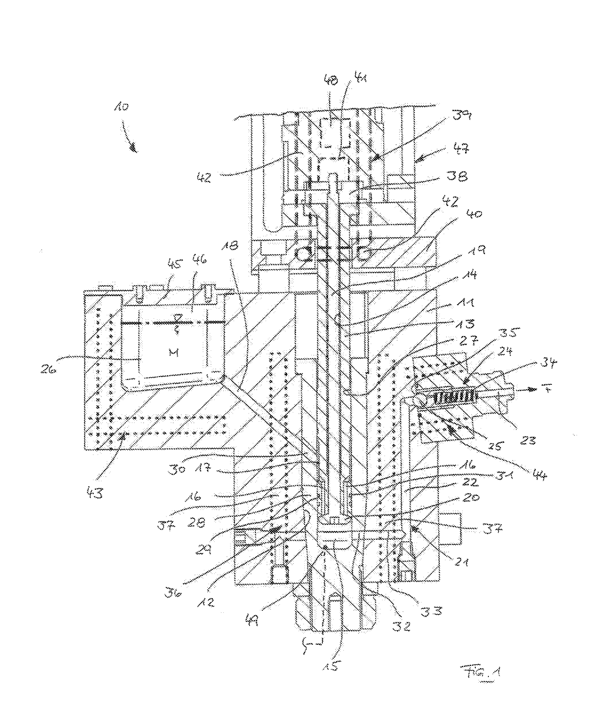
[0025]Referring to the drawings, a feed device 10 for a metal melt M in an injection molding device, which feed device is shown in FIG. 1, has a housing 11, in which a vertical receiving hole 12 is formed.

[0026]A reservoir 26, which is filled with the metal melt M, is provided in the housing 11. The metal melt M may be fed to the reservoir 26 in the molten form or produced in this by melting, for example, metal granules.

[0027]The reservoir 26 is covered airtightly by means of a cover part 45 and the free space 46 formed above the metal melt M in the reservoir 26 is filled with a protective gas, for example, carbon dioxide (CO2) or nitrogen (N2).

[0028]A second heater 43, which may be an electrical resistance heater and with which the wall of the reservoir 26 and hence the metal melt M can be brought to a desired temperature or maintained at such a temperature, is integrated in the housing 11 in the area of the reservoir 26.

[0029]Via at least one feed channel 18 extending with a downw...


PUM

PropertyMeasurementUnit
Circumferenceaaaaaaaaaa

Abstract

A feed device for a metal melt in an injection molding device of, for example, a metal-molding machine has a reservoir for the metal melt and a feed duct, in which the metal melt can be fed to a mold cavity. The feed duct includes a cylinder bore, in which a piston is arranged axially displaceably. A collection chamber for the metal melt, from which the metal melt can be introduced into the mold cavity through a continuing line as a consequence of an axial displacement of the piston, is provided in the cylinder bore. The cylinder bore is surrounded by a first heater, which has at least one heating element.

Description

CROSS REFERENCE TO RELATED APPLICATIONS[0001]This application is a United States National Phase Application of International Application PCT / EP2015 / 002517, filed Dec. 15, 2015, and claims the benefit of priority under 35 U.S.C. §119 of German Application 10 2014 018 798.5, filed Dec. 19, 2014, the entire contents of which are incorporated herein by reference.FIELD OF THE INVENTION[0002]The present invention pertains to a feed device for a metal melt in an injection molding device, with a reservoir for the metal melt and with a feed duct, in which the metal melt can be fed to a mold cavity, wherein the feed duct comprises a cylinder bore, in which a piston is arranged axially adjustably, and wherein a collection chamber is provided for the metal melt in the cylinder bore, and the metal melt can be introduced from the collection chamber into the mold cavity through a continuing line as a consequence of an axial displacement of the piston.BACKGROUND OF THE INVENTION[0003]A molten metal...

Claims


Application Information

Patent Timeline
IPC IPC(8): B22D17/04B22D17/20B22D17/30B22D17/32
CPCB22D17/04B22D17/2023B22D17/32B22D17/2038B22D17/30B22D17/203
Inventor BREXELER, INGO
Owner GEBR KRALLMANN
Why Eureka
Try Eureka