Injection molding tool and method for producing a molded part

a technology of injection molding and molding parts, which is applied in the direction of tubular articles, domestic applications, other domestic articles, etc., can solve the problems of together leading to scratches and scuffs, and achieve the effects of reliable determination of target distance, high quality, and considerable stability

Active Publication Date: 2017-12-07
GERRESHEIMER REGENSBURG GMBH
View PDF6 Cites 0 Cited by
  • Summary
  • Abstract
  • Description
  • Claims
  • Application Information

AI Technical Summary

Benefits of technology

[0014]An advantage of the invention is that a reliable determination of a target distance between the front topology of the first slider and the edge topology of the second slider is possible. It is only by means of this safe determination of the target distance that it is possible for the first slider and the second slider to move apart without damage. This ensures that the edge topology of the second slider does not slide on the front topology of the first slider during disassembly and thus leads to damage. As a result of this, an injection molding tool is obtained which has a considerable stability and thus provides a tool with which high-quality molded parts can be produced by means of an injection molding process.
[0015]With the method according to the invention for producing a molded part in an injection molding tool, it is possible to produce molded parts with high quality over a longer period of time. The method comprises a plurality of steps. At first, the injection mold tool is closed, so that the first tool mold half and the second mold half are arranged opposite one another. Then, the first slider and at least one second slider are inserted into the first tool mold half and into the second tool mold half. This creates a free space for the molded part to be produced. When the first slider and the second slider are inserted into the first tool mold half and into the second tool mold half, a front topology of the first slider fully lies against an edge topology of the second slider. Subsequently, an injection molding of a liquefied material into the free space is carried out, thus forming the molded part. Before the molded part can be ejected from the injection mold, it is necessary that the front topology of the first slider be separated from the edge topology of the second slider or that they can be moved apart at a distance. The first slider is coupled to a pretensioned lever in order to ensure a sufficient distance between the first slider and the second slider. By means of the pretensioned lever, which cooperates with an end switch, it is thus possible to determine a target distance between the front topology of the first slider and the edge topology of the second slider. With a movable end of the pretensioned lever, the target distance at an end switch is transmitted into a greater distance. As a result of the transmission into the greater distance, it is then ensured that the target distance is achieved, so that a complete withdrawal of the first slider and of the at least one second slider is possible without damage. Finally, the injection mold tool is opened and the molded part is ejected.
[0016]According to an embodiment of the invention, the target distance between the front topology of the first slider and the edge topology of the second slider should be at least 0.2 mm. The pretensioned lever is configured in such a way that the greater value of the target distance between the movable end of the pretensioned lever and the end switch is 0.95 mm.
[0017]With the transmission through the pretensioned lever, the movable end of which cooperates with the end switch, it can be ensured that the required target distance between the front topology of the first slider and the edge topology of the second slider is achieved. It is thus possible to ensure that the first slider and the second slider are moved apart without damage and thus no slipping or grinding of the front topology of the first slider and the edge topology of the second slider is possible.

Problems solved by technology

Since the surfaces of the cores or sliders are highly polished, this sliding together leads to scratches and scuffs.

Method used


Image

  • Injection molding tool and method for producing a molded part
  • Injection molding tool and method for producing a molded part
  • Injection molding tool and method for producing a molded part

Examples


Embodiment Construction

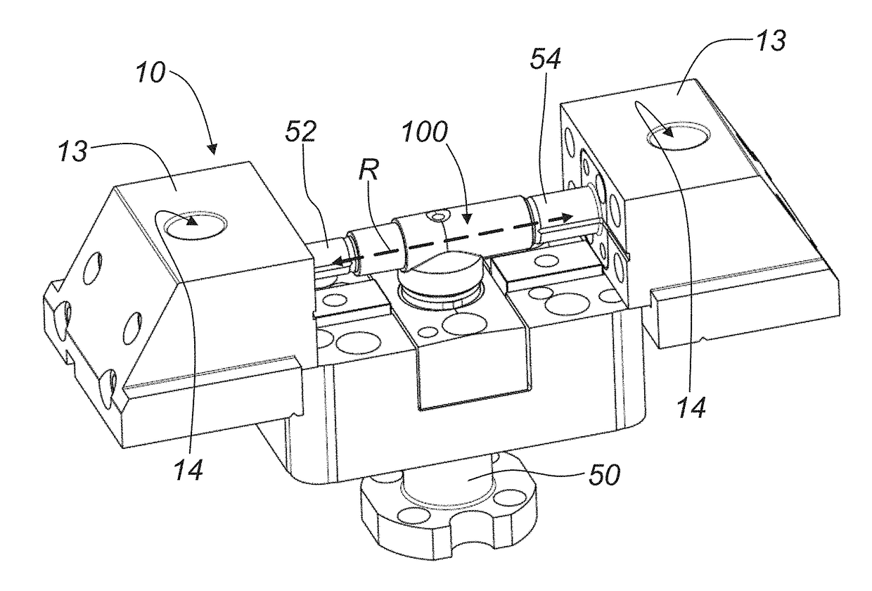
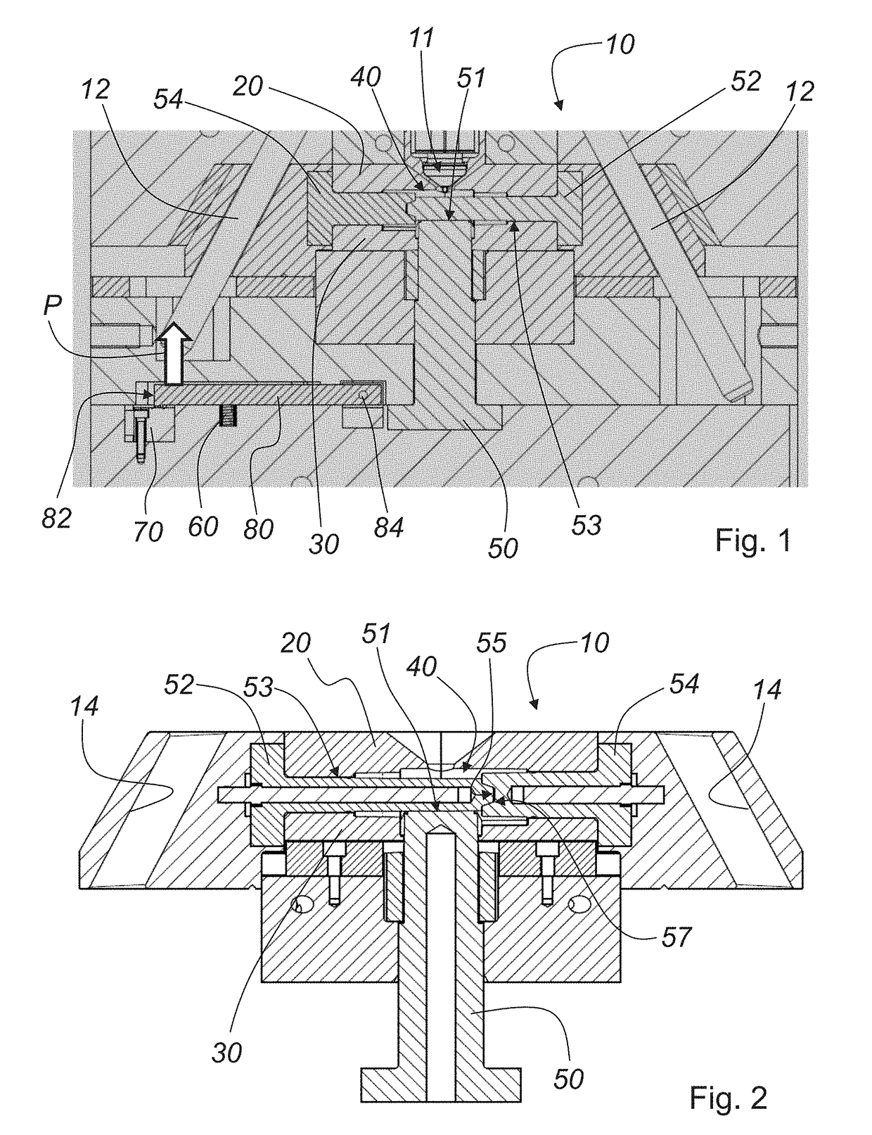
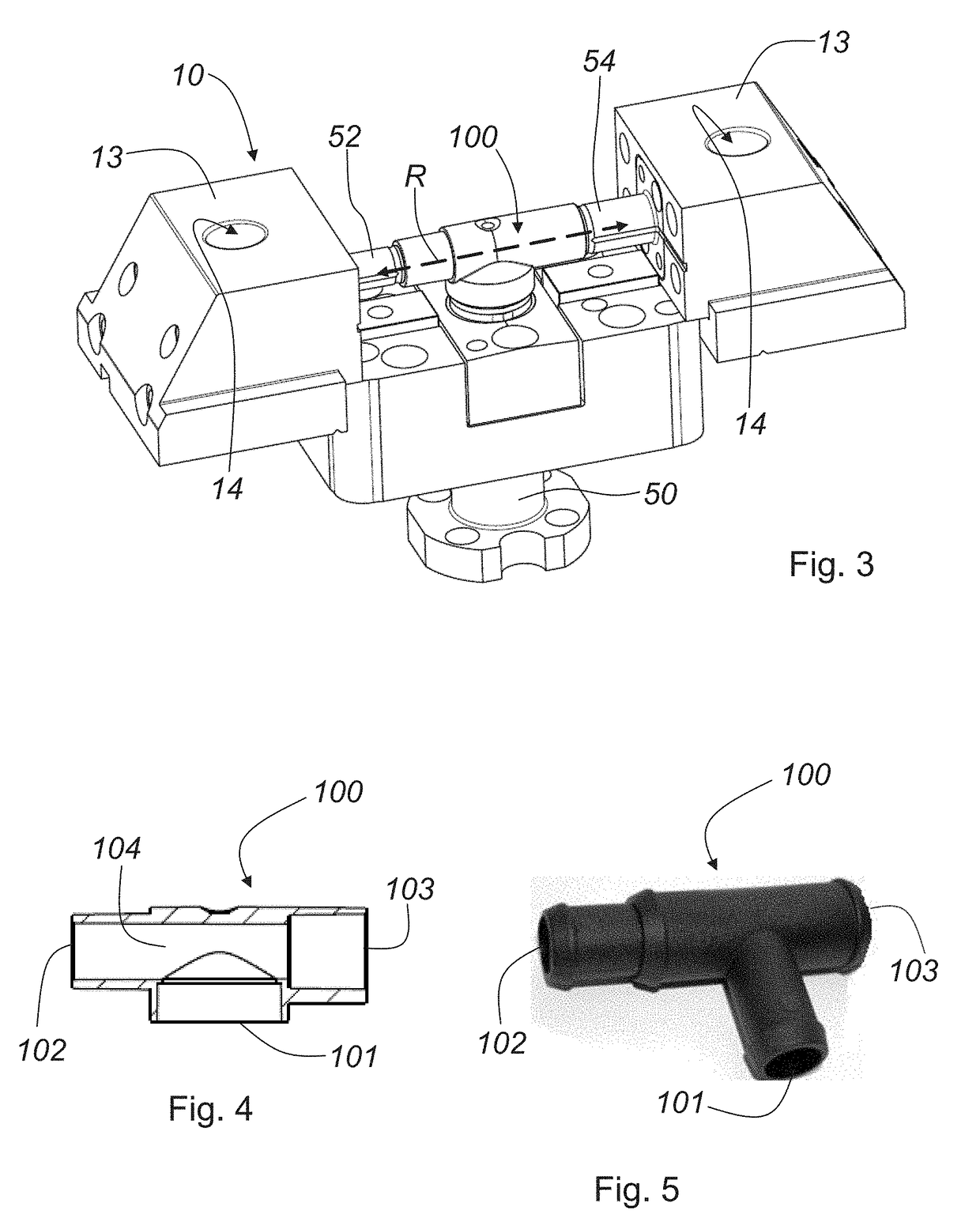
[0027]FIG. 1 shows a cross-section through an injection molding tool 10, in which a pretensioned lever 80 cooperates with an end switch 70. Molded parts 100 (see FIGS. 4 and 5) are produced with the injection molding tool 10 according to the invention. In the embodiment described here, the injection molding tool 10 comprises a first tool mold half 20 and a second tool mold half 30. A first slider 50, a second slider 52 and a third slider 54 are inserted into the tool mold halves 20, 30. The first slider 50, the second slider 52 and the third slider 54, together with the first tool mold half 20 and the second tool mold half 30, form a free space 40. Said free space 40 serves to form the molded part 100 which is to be produced by the injection molding process. In the inserted state, a front topology 51 of the first slider 50 is engaged with an edge topology 53 of the second slider 52 in a form-fit manner. A front end 55 (see FIG. 2) of the second slider 52 abuts a front end 57 (see FI...


PUM

PropertyMeasurementUnit
distanceaaaaaaaaaa
distanceaaaaaaaaaa
distanceaaaaaaaaaa

Abstract

An injection molding tool for producing a molded part and a corresponding method are disclosed. The injection mold tool comprises a first tool mold half and a second tool mold half, which together with a first slider and at least one second slider define a free space for the molded part to be produced. A lever which is pretensioned with an elastic element is assigned to an end switch such that a movable and free end of the lever cooperates with the end switch due to a movement of the first slider.

Description

[0001]This nonprovisional application claims priority under 35 U.S.C. §119(a) to German Patent Application No. 10 2016 110 168.0, which was filed in Germany on Jun. 2, 2016, and which is herein incorporated by reference.BACKGROUND OF THE INVENTIONField of the Invention[0002]The invention relates to an injection molding tool for producing a molded part. In particular, the injection molding tool comprises a first tool mold half and a second tool mold half which, together with a first slider and at least one second slider, define a free space for the molded part to be produced. The first slider has a front topology. Likewise, the second slider has formed an edge topology. The front topology of the first slider thereby lies fully against the edge topology of the second slider when the first slider and the second slider have entered the injection mold tool. An end switch is used to determine a distance between the front topology of the first slider and the edge topology of the second sli...

Claims


Application Information

Patent Timeline
Patent Type & Authority Applications(United States)
IPC IPC(8): B29C45/84B29C45/80B29C45/26B29C45/40B29C45/76B29L23/00
CPCB29C45/84B29C45/80B29C45/261B29C45/7626B29L2023/22B29C2945/76096B29C2945/76418B29C2945/76581B29C45/40B29C45/26B29C45/2602B29C45/33B29C2945/76254B29C2945/7627B29C2945/76394B29C45/2628B29C45/2673
Inventor HUTTER, JOSEFLINDNER, SANDRA
Owner GERRESHEIMER REGENSBURG GMBH
Why Eureka
Try Eureka