Ejection seat

a technology for ejection seats and seats, which is applied in the direction of aircraft ejection means, support/holding devices, etc., can solve the problems of head and/or limbs, affecting the motion of seats, and the occupant might not be seated in the optimal position of the ejection sea

Active Publication Date: 2017-12-07
MARTIN BAKER AIRCRAFT
View PDF6 Cites 8 Cited by
  • Summary
  • Abstract
  • Description
  • Claims
  • Application Information

AI Technical Summary

Benefits of technology

The patent describes a system where a tether is connected between an aircraft and its cockpit with a weak joint that will disconnect at a predetermined force. This helps to protect the tether and ensure safe operation of the aircraft.

Problems solved by technology

The technical problem addressed in this patent is to ensure that the occupant of an ejection seat is in an optimal position and minimizes the risk of injury or injury to the pilot or equipment in the cockpit during the ejection procedure. This is important because an out-of-position occupant could be at greater risk of injury from the wind force and impact with the cockpit or equipment.

Method used


Image

  • Ejection seat
  • Ejection seat
  • Ejection seat

Examples


second embodiment

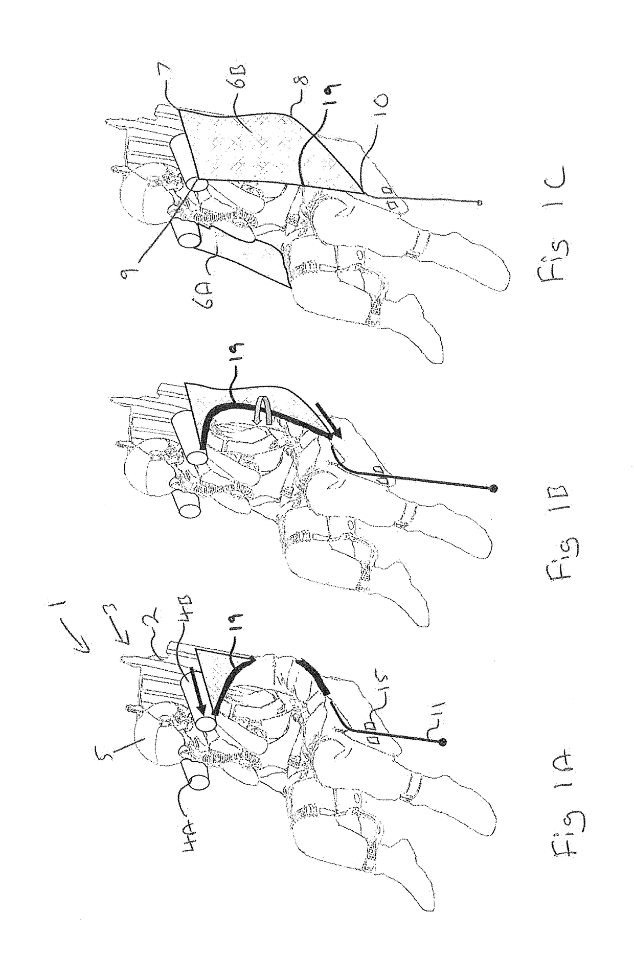
[0083]FIGS. 3A-3C illustrate an ejection seat 20 according to the present invention. Like numerals are used to refer to like features.

[0084]The ejection seat 20 comprises a seat back 2 and a headrest assembly 3 mounted to or forming part of the seat back 2.

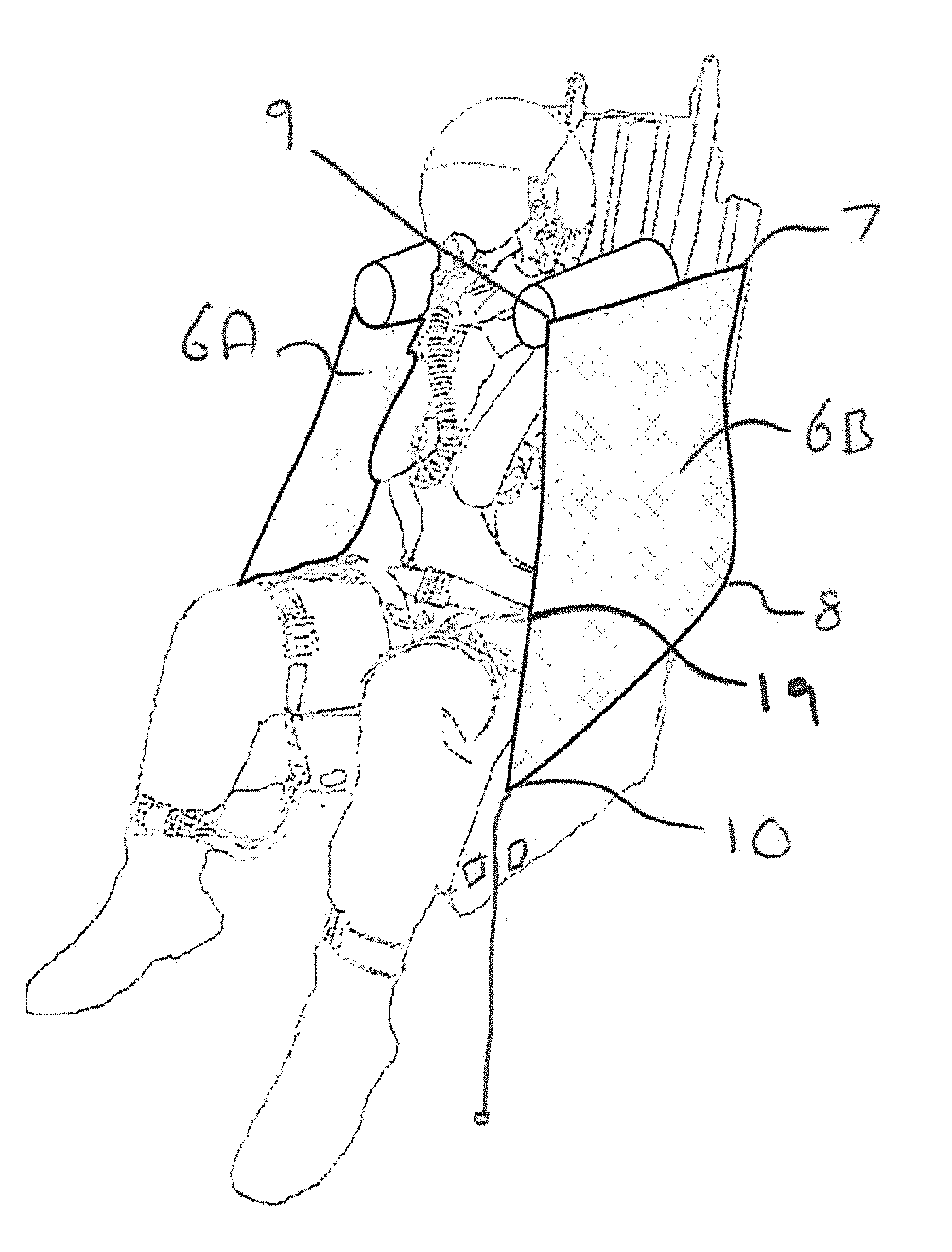
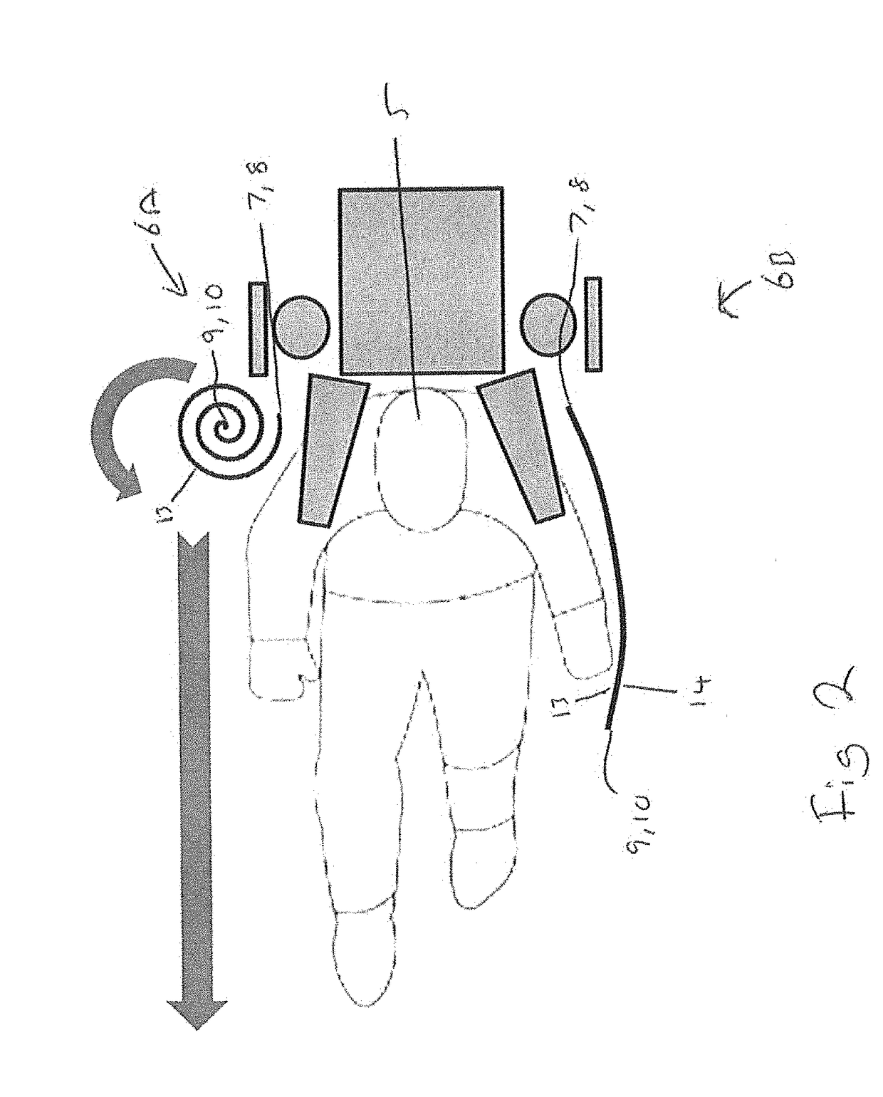
[0085]The ejection seat 20 further comprises first 40A and second 40B head support beams, both stowable in the headrest assembly 3 and configured to be deployed through a capturing phase in which they project upwardly from the headrest assembly 3, into a retention phase in which they project forwardly from the headrest assembly 3, for capturing a seat occupant's head 5 therebetween.

[0086]The ejection seat 20 further comprises first 6A and second 6B arm retention curtains. The arm retention curtains of the ejection seat 20 may be substantially the same as those of ejection seat 1.

first embodiment

[0087]The first head support beam 40A and the first arm retention curtain 6A are provided on a first side of the seat back 2. With reference to FIG. 3A, the first side of the seat back may be referred to as the “left hand side” of the seat. The second head support beam 40B and the second arm retention curtain 6B are provided on a second side of the seat back 2, which may be referred to as the “right hand side” of the seat 2. In use, the occupant is seated between the first and second (left and right) side of the seat back 2. As with the first embodiment, when the head support beams 40A, 40B are deployed, they serve to capture the occupant's head 5 therebetween. The curtains substantially capture the occupant's arms.

[0088]A first tether 51A is secured at a first end 52A to the first retention curtain 6A and removably secured, in turn, to the distal ends of the first 40A and second 40B head support beams respectively. The second end 53A of the first tether 51A is arranged to be drawn ...


PUM


Abstract

An ejection seat is disclosed comprising a seat back; a headrest assembly mounted to or forming part of the seat back; a pair of head support beams stowable in the headrest assembly, configured to be deployed such that they project forwardly from the headrest assembly, for capturing a seat occupant's head therebetween, and a pair of arm retention curtains, wherein at least part of each arm retention curtain is stowed in a rolled condition, configured such that deploying the head support beams and/or drawing the tethers forward from the seat back unfurls the arm retention curtains.

Description


Claims


Application Information

Patent Timeline
Owner MARTIN BAKER AIRCRAFT
Why Eureka
Try Eureka