Helicopter blade emergency detachment system

a technology of helicopter blades and detachments, which is applied in the field of helicopter blades, can solve the problems of not being able to easily rotate, and not being widely adopted by helicopter occupants

Inactive Publication Date: 2007-03-01
BOICE WILLIAM SPENCER +2
View PDF4 Cites 6 Cited by
  • Summary
  • Abstract
  • Description
  • Claims
  • Application Information

AI Technical Summary

Benefits of technology

The patent describes an improved design for an ignition training system used by helicopters. This system uses multiple parts including detosionting cord, disarming interlinks, a manifold for distributing signals to different blades, and redundant detosionding cords. These features help ensure that the system works reliably even under high-stress conditions.

Problems solved by technology

This patent discusses how helicopters have special abilities compared to regular planes because they can move in different directions at once. They're faster and work better under various circumstances. However, if something happens during flight like losing all engines, helicopters don't always know what to do. They rely on a process calledautorotation which allows them to land safely without breaking their wings. But sometimes, this doesn't happen either. So, the technical problem being addressed by this patent is finding ways for helicopters to quickly and efficiently evacuate passengers in case of emergencies while still maintaining safe flying standards.

Method used


Image

  • Helicopter blade emergency detachment system
  • Helicopter blade emergency detachment system
  • Helicopter blade emergency detachment system

Examples


Embodiment Construction

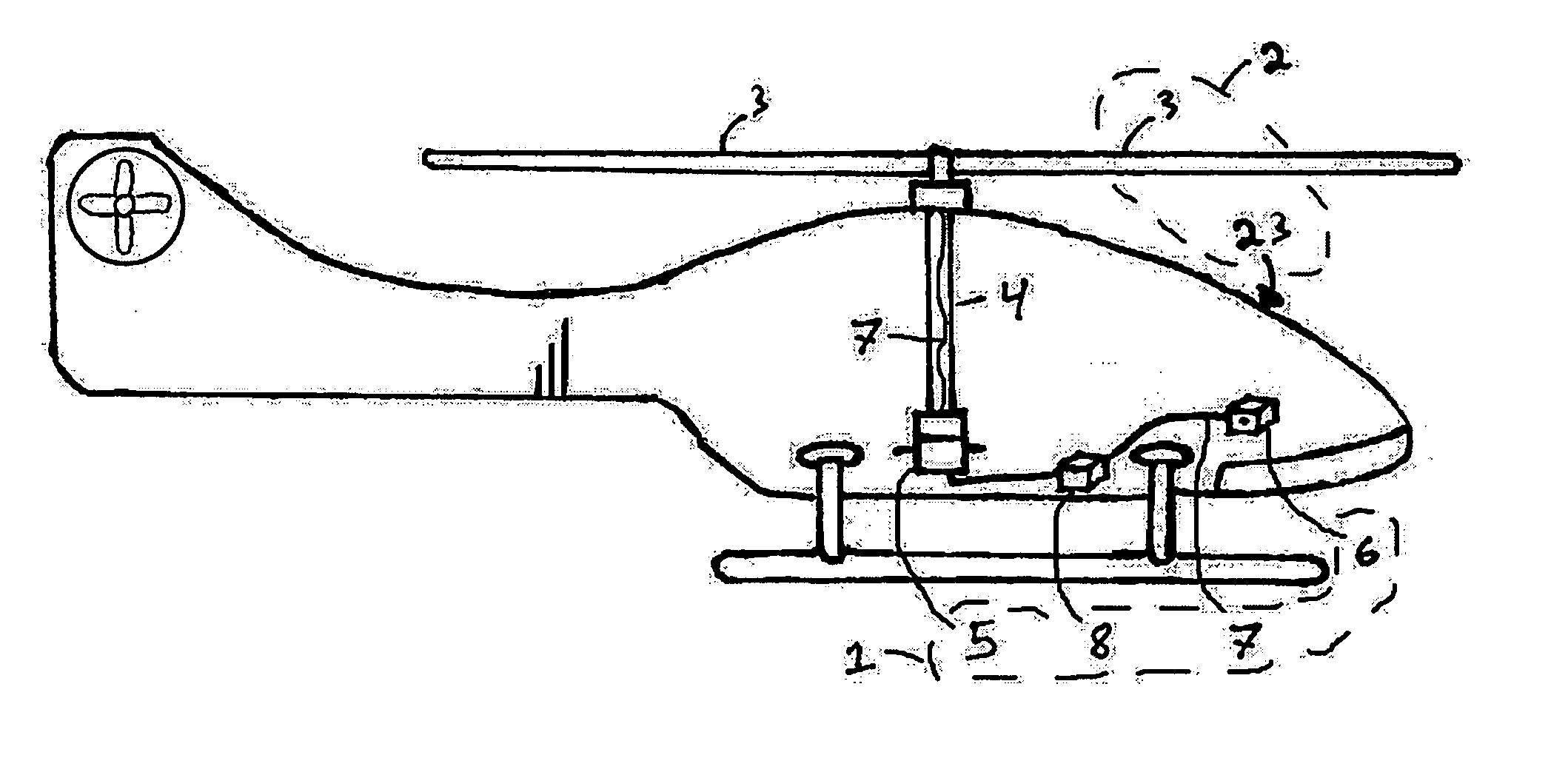
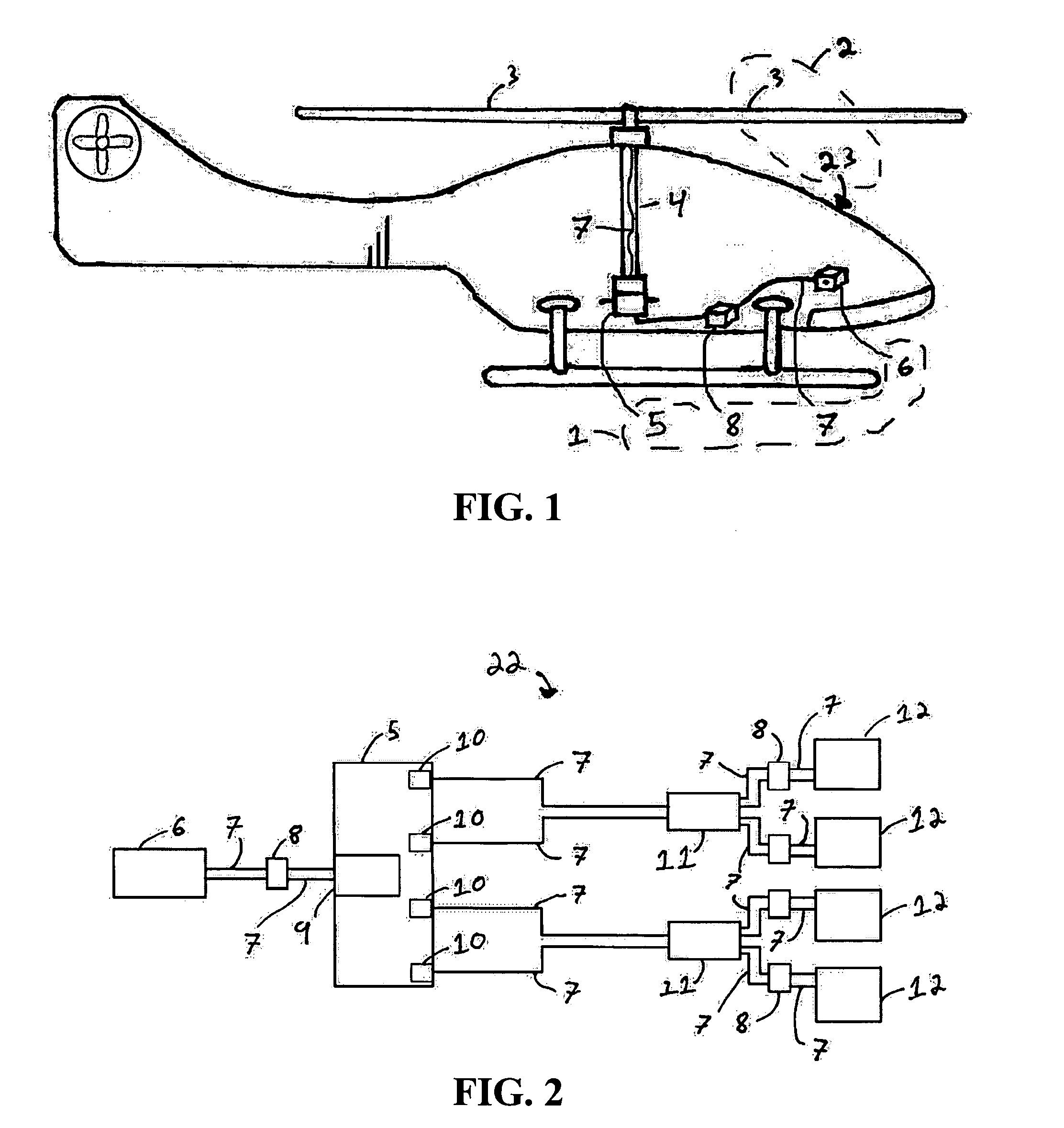
[0020] With reference now to the figures, and in particular to FIG. 1, there is depicted a preferred embodiment of a helicopter blade emergency detachment system 1, shown in further detail in FIGS. 2-6, that includes a signal initiator 6 (preferably mounted in the cockpit of helicopter 2), a transfer system 5, an ignition train 22 (shown in FIG. 2), and linear shaped charges 12 (shown, inter alia, in FIG. 5) placed inside the blade 3.

[0021] The helicopter 2 includes a fuselage 23 and blades 3. While the fuselage can remain stationary during flight, the blades are constantly spinning around it and never come to a rest. This leads to the need for a transfer system 5 to enable the activation signal from the pilot to move between the two parts of the helicopter. However, before the transfer system can be used, the pilot must activate the helicopter blade emergency detachment system by pulling a lever, flicking a switch, or pushing a button on the signal initiator 6 which is a mechanica...


PUM


Abstract

A method and system for a helicopter blade emergency detachment system that has an activator in the cockpit to initiate the system, an ignition train to provide the detonation signal, a transfer system at the base of the main rotor shaft to move the signal from the stationary helicopter to the rotating blades, and explosive charges located at the root of each main bearing-less rotor blade to separate the composite blade from the main rotor. These four components interact in the way described to enable the blades of the helicopter to be detached during an emergency, thus increasing the stability of the aircraft during a hard landing and/or allowing for the use of an occupant ejection seat or parachute while the helicopter is still in flight.

Description


Claims


Application Information

Patent Timeline
Owner BOICE WILLIAM SPENCER
Why Eureka
Try Eureka