Door system for transit vehicle utilizing compression lock arrangement

a technology for transit vehicles and doors, applied in the field of transit vehicle door systems, can solve the problems of unrestricted pushback, undesirable incremental longitudinal movement of doors, and compromising the sealing capabilities of the door system, so as to improve the reliability of the lock mechanism operation, reduce the number of locking operations, and protect against environmental factors

Inactive Publication Date: 2007-06-12
WESTINGHOUSE AIR BRAKE TECH CORP
View PDF10 Cites 17 Cited by
  • Summary
  • Abstract
  • Description
  • Claims
  • Application Information

AI Technical Summary

Benefits of technology

[0024]The present invention teaches a door system, particularly for a transit vehicle, having at least one door with a sealing means disposed at leading edge thereof. A door drive means is disposed within the transit vehicle for moving the door in an opening and a closing direction. A brake is attached to either an output shaft of the prime mover or the drive spindle for preventing rotation of the drive spindle, thus maintaining the door in a substantially closed and locked position and for maintaining a compression of the sealing means. The door drive means includes a drive spindle, a prime mover having an output shaft attached to one end of the drive spindle with a coupling means, a drive nut collared around the drive spindle, a drive guide member disposed substantially parallel to the drive spindle and at least one hanger bracket attached to the door and connected to the drive nut for enabling its substantially linear movement upon rotation of such drive spindle in the closing and the opening direction, and further enabling movement of the door. A door control unit provides various signals to the prime mover and brake and receives various status and position annunciation signals as well as door open and door close commands. A mechanical lock is provided to positively lock the door thus providing redundancy of a locking operation. The utilization of the brake enables avoiding a preload of the movable locking member against the stationary locking member thus improving reliability of the lock mechanism operation. A manual release is provided to enable manual opening of the door in an emergency condition or for maintenance purposes. Compression of the sealing means maintains superior protection against environmental factors such as moisture, noise and dust as well as prevent component vibration due to tolerance and wear. Various annunciation means are incorporated to provide position and status feedback to the door control unit. Combination of the brake and lock mechanism eliminates any possibility for unintentional door opening due to a single component failure.OBJECTS OF THE INVENTION
[0028]Another object of the present invention is to provide a lock arrangement for a door system of a transit vehicle which enables redundancy of maintaining the door in a closed and locked position.
[0029]Still another object of the present invention is to provide a lock arrangement for a door system of a transit vehicle which eliminates the vibration of the door system due to tolerances and component wear.

Problems solved by technology

This manual movement does not require an action by a drive element disposed within powered door drive means and generally does not provide a signal to the control system of the transit vehicle.
However, the significant disadvantage of the spring pushback is unrestricted and undesirable incremental longitudinal movement of the door during transit vehicle motion, particularly, as the spring fatigues over time.
This undesirable movement compromises the sealing capabilities of the door system.
The difficulties of such an arrangement lie in that the lock mechanism must overcome additional frictional forces during locking and unlocking sequences.
Tolerances of the rubber edge elements, general door system tolerances and environmental factors affect the engagement between such rubber edge elements resulting in either a frequent need for lock mechanism adjustments and fine tuning, decreased sealing capabilities, or decreased reliability of the lock mechanism operation.
There are several disadvantages to the prior art design disclosed in U.S. Pat. No. 6,189,285.
Such components increase the complexity and cost of the door system and reduce its reliability.
The disclosure does not teach means for detecting and annunciating such failures.
Therefore, the prior art design does not provide locking redundancy in preventing unintentional opening of the door (1, 2) of the sliding or sliding pocket type.
In a third aspect, the described locking arrangement does not provide for combination of locking the door (1, 2) in the pushback mode and enabling claimed sealing advantages due to presence of the freewheel (23) and receptacle (22).

Method used


Image

  • Door system for transit vehicle utilizing compression lock arrangement
  • Door system for transit vehicle utilizing compression lock arrangement
  • Door system for transit vehicle utilizing compression lock arrangement

Examples


Embodiment Construction

, particularly, when the detailed description is taken in conjunction with the attached drawing figures and with the appended claims.

BRIEF DESCRIPTION OF THE DRAWINGS

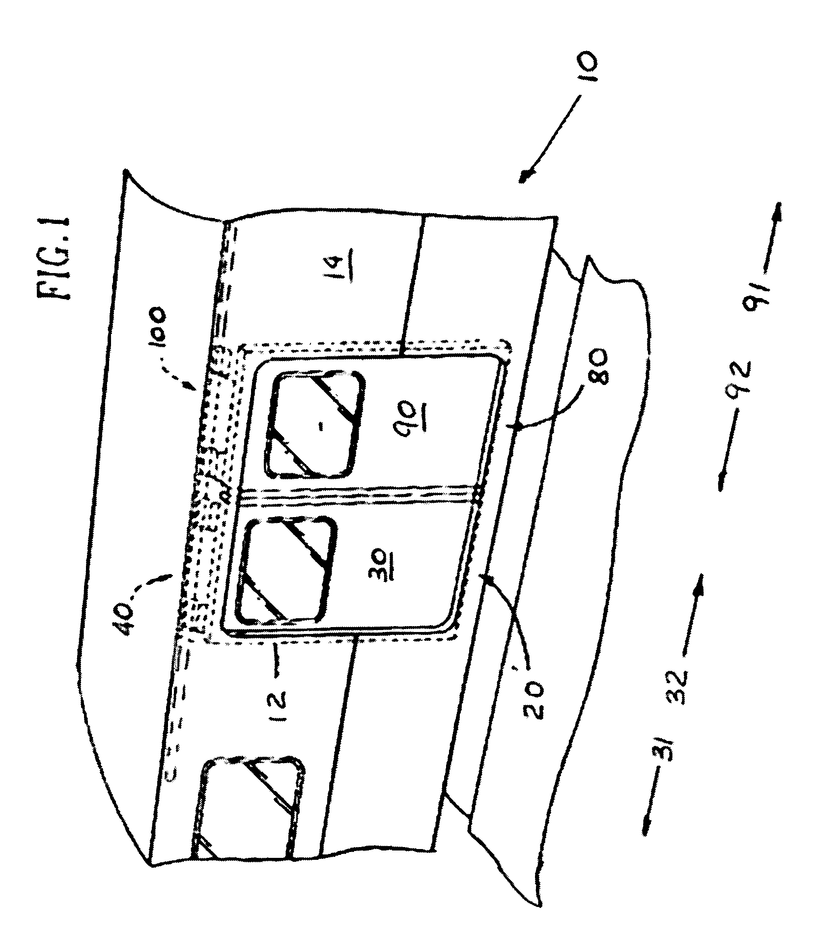
[0032]FIG. 1 is a partial perspective view of a typical transit vehicle door system.

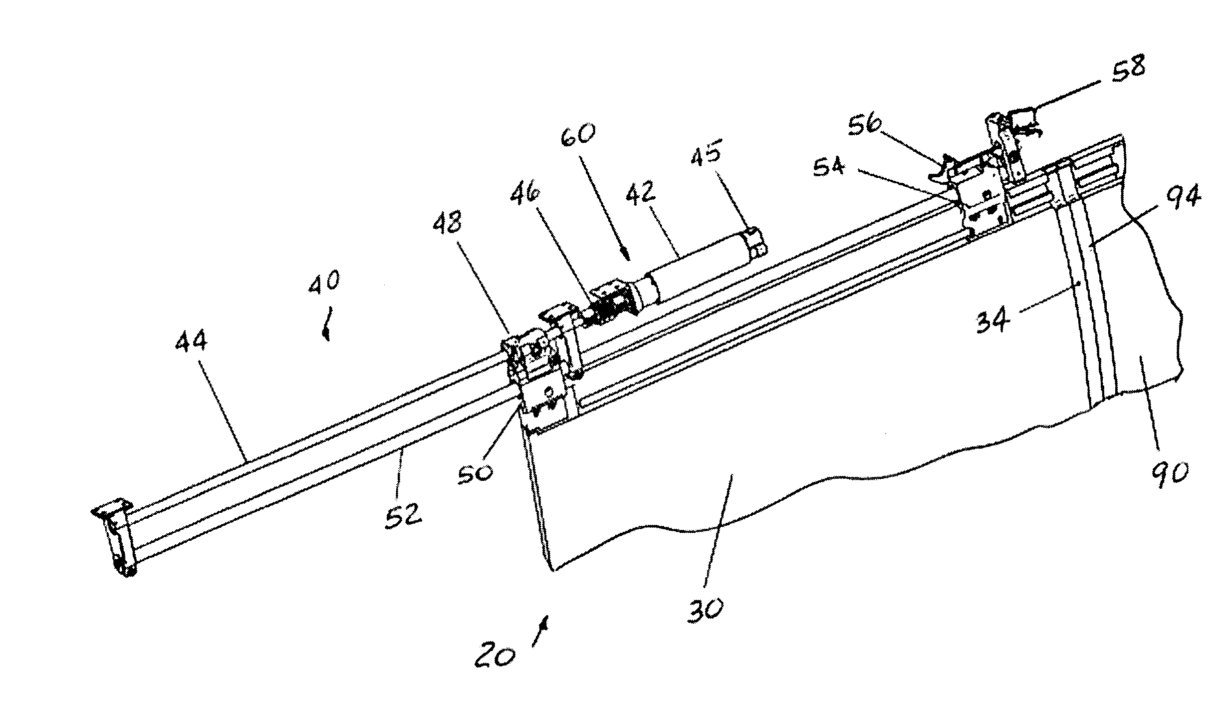
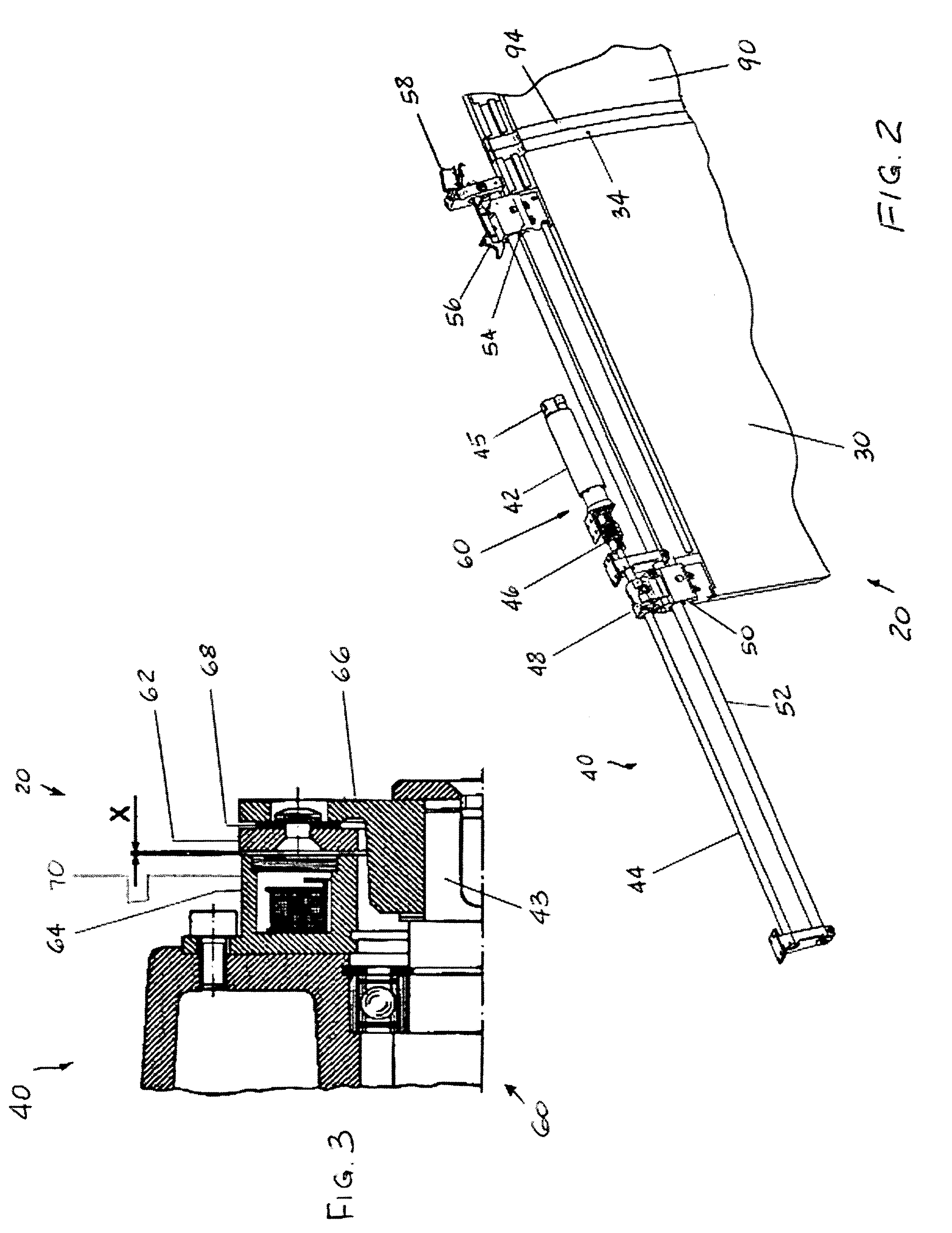
[0033]FIG. 2 is a partial perspective view of the door system, particularly showing a powered door drive means and door.

[0034]FIG. 3 is a partial cross-sectional plan view of the electromagnetic brake.

[0035]FIG. 4 is a schematic illustration which shows an embodiment of the invention connected to the door system control unit.

[0036]FIG. 5 is a partial cross-sectional elevation view of the prior art design.

DESCRIPTION OF THE PRESENTLY PREFERRED AND VARIOUS ALTERNATIVE EMBODIMENTS OF THE INVENTION

[0037]Before describing the invention in detail, the reader is advised that, for the sake of clarity and understanding, identical components having identical functions have been marked where possible with the same reference numerals in each of the ...


PUM


Abstract

A locking arrangement for a door system of a transit vehicle includes a combination of a lock mechanism and an electromagnetic brake. The lock mechanism enables positive locking of at least one door but does not require substantial contact between moving and stationary lock elements. The lock mechanism is connected with the manual release means for door opening during an emergency. The electromagnetic brake maintains door seal compression in the closed and locked condition which improves sealing capabilities and provides for reliable lock mechanism operation. Such combination provides locking redundancy and meets various requirements regarding annunciation and manual release operation.

Description

FIELD OF THE INVENTION[0001]The present invention relates, in general, to a door system for transit vehicles and, more particularly, the instant invention relates to transit vehicle door systems employing locking arrangements for locking one or two doors in either a pushback or non-pushback mode.BACKGROUND OF THE INVENTION[0002]The following background information is provided to assist the reader to understand the environment in which the invention will typically be used. The terms used herein are not intended to be limited to any particular narrow interpretation unless specifically stated otherwise in this document.[0003]Powered door systems have been extensively utilized in various vehicle applications. Specifically, it is well known in the transit vehicle art to employ a door system having a powered door drive means and a lock mechanism for locking at least one door connected to such powered door drive means and driven thereby to at least partially cover and uncover a door portal...

Claims


Application Information

Patent Timeline
Patent Type & Authority Patents(United States)
IPC IPC(8): B61D3/00E05B65/08E05B65/12E05F15/00E05F15/10E05F15/14E05F15/56E05F17/00
CPCE05B77/00E05F15/655E05B83/363E05B83/40E05F15/40E05F15/652E05Y2201/216E05Y2201/22E05Y2201/234E05Y2201/246E05Y2201/434E05Y2800/112E05Y2900/51E05Y2800/00E05Y2201/21E05Y2201/438E05Y2201/462E05Y2201/64E05Y2201/214E05F15/56E05F15/632E05F17/00
Inventor STOJC, ANDREEVANS, SIMON
Owner WESTINGHOUSE AIR BRAKE TECH CORP
Why Eureka
Try Eureka