
Protection of devices in a redundant configuration

a technology for protecting devices and configurations, applied in the direction of electric controllers, instruments, ignition automatic control, etc., can solve the problems of card not responding, active card activity latch cannot be released, active card becomes entirely unreachable from the management interface,

Active Publication Date: 2008-10-14
CIENA
View PDF4 Cites 18 Cited by
  • Summary
  • Abstract
  • Description
  • Claims
  • Application Information

AI Technical Summary

Benefits of technology

The present invention provides a device with a control processor, a reset module, and a monitor for monitoring the control status of the device. The device can still be reset even if the control processor malfunctions, and the monitor can control the reset module independently. The device can also communicate with another device to take over its functions in case of a malfunction. The device can generate its own reset signal to reset another device, and the notification interface can send a notification to another device based on the monitored condition. The device can also be connected to a management interface or a redundant device for protection. The technical effects of the invention include improved reliability and responsiveness of the device, as well as increased redundancy for protection purposes.

Problems solved by technology

One problem that has been encountered with the present configuration is that under certain fault conditions, the active card becomes entirely unreachable from the management interface, and the active card does not respond to the activity release message.
In this event, the activity latch of the active card cannot be released and the redundant card cannot be activated to resume the communication functions of the active card.
In this case, customers may experience significant disruptions to the communication service while the line card is down and maintenance staff are sent out into the field to rectify the fault.

Method used


Image

  • Protection of devices in a redundant configuration
  • Protection of devices in a redundant configuration
  • Protection of devices in a redundant configuration

Examples


Embodiment Construction

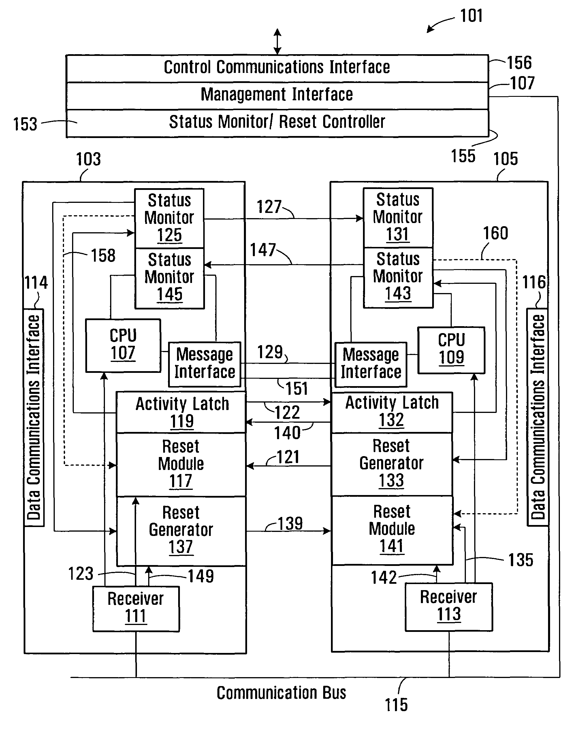
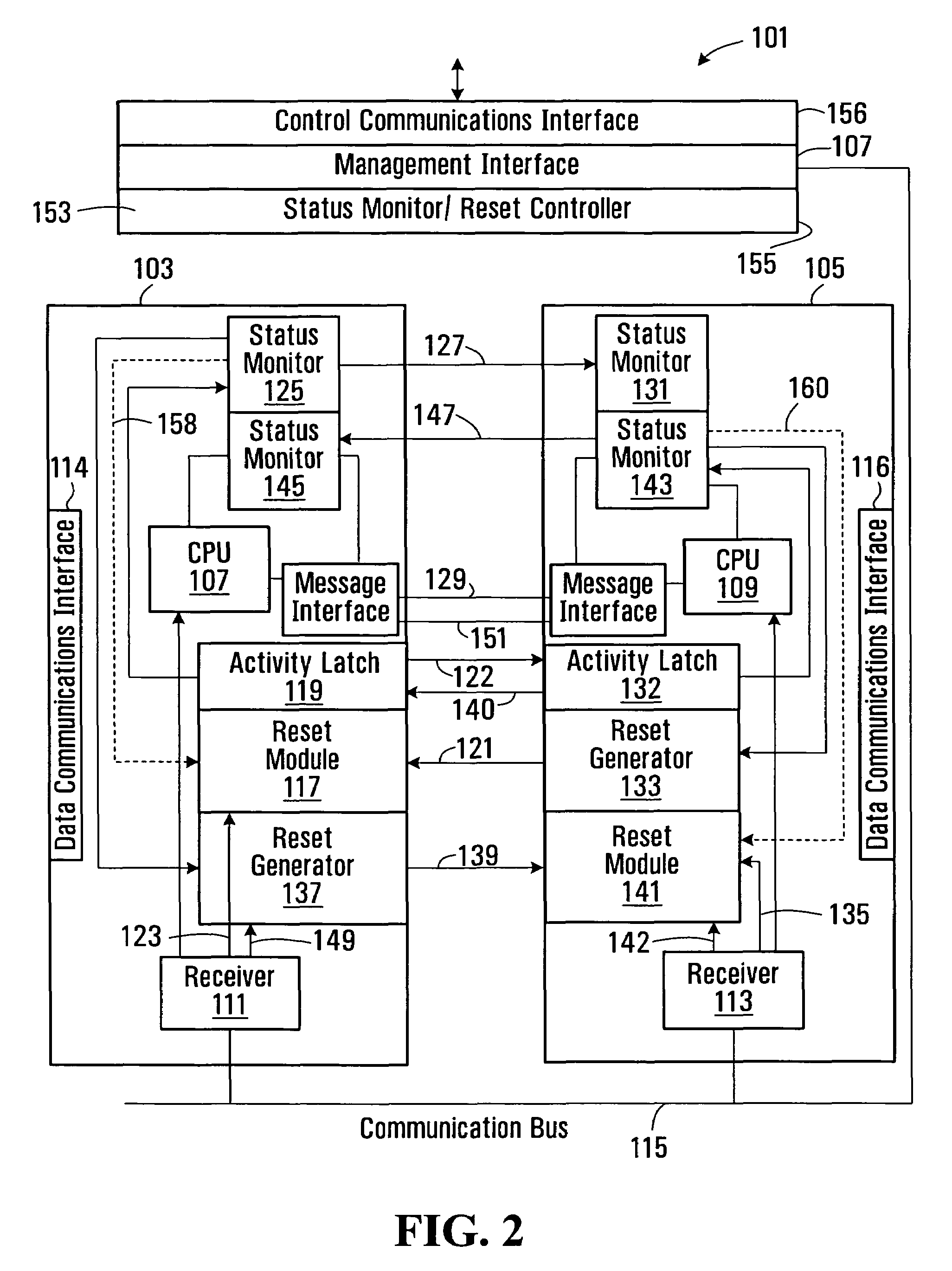
[0029]Referring to FIG. 2, a protected circuit arrangement 101, according to an embodiment of the present invention comprises a first line card 103, which is normally active, a second line card 105, which is normally inactive and is provided to protect the active line card 103 in the event of a malfunction, and a management interface 107. The first and second line cards each comprise a control processor 107, 109 (or controller) for controlling operations of the respective card. Each card also comprises a receiver 111, 113 for receiving data from a communication bus 115 and passing relevant control data to its respective control processor 107, 109. Each card also includes a data communication interface 114, 116 for connection to a data communication network (not shown).

[0030]The first line card 103 further comprises a reset module 117 which is adapted to be controlled independently of the control processor 107 for performing a reset operation of the card. The reset operation may incl...


PUM


Abstract

A network communication device is provided, comprising a control processor for controlling operation of the device, a reset module which is controllable independently of the control processor for performing a reset operation of the device, and a reset control interface for receiving a reset signal, the reset module being responsive to the reset signal for performing the reset operation. A monitor is provided for monitoring the status of the control processor and an interface is adapted to transmit information relating to the monitored status from the device. A second, inactive device is provided to protect the communication device in the event of a control fault which renders the communication device unreachable. The protection device includes a reset interface for transmitting a reset signal to the reset module to enable the communication device to release activity.

Description

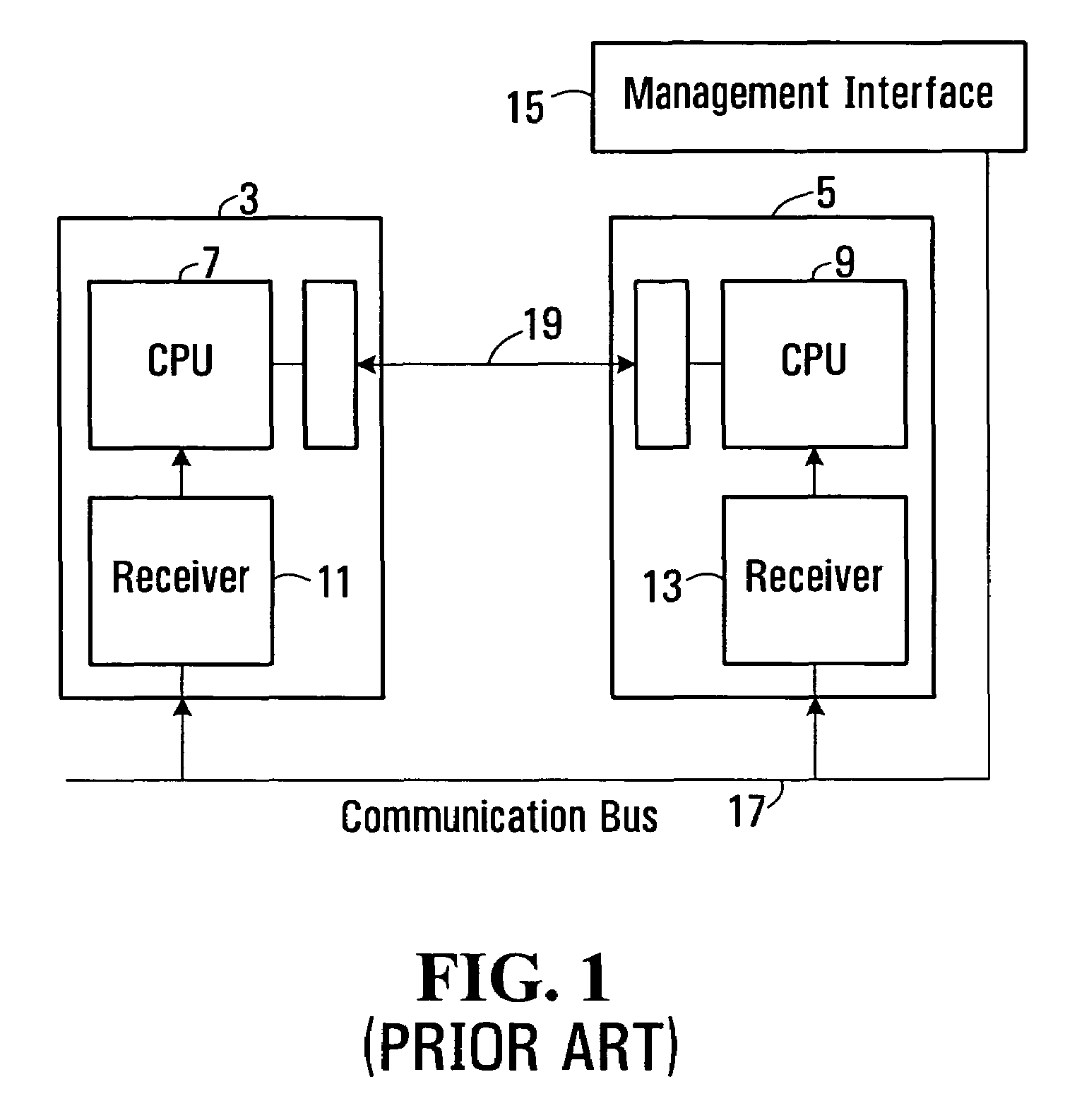
FIELD OF THE INVENTION[0001]The present invention relates to protection of devices in a redundant configuration and in particular, but not limited to, the protection of communication devices such as line or circuit cards.BACKGROUND OF THE INVENTION[0002]Line cards for communication systems provide an interface for connecting communication elements to a network and typically include a number of communication ports for transmitting and receiving communication traffic to and from the network. In one configuration, an additional line card is provided for each active line card of a network element to protect the active card in the event of a fault or failure. The additional line card is typically identical to the active card and is capable of assuming and performing the functions of the active card, if the active card malfunctions, so that disruptions in communication are reduced while the active card is replaced or repaired.[0003]An example of a redundant line card configuration is show...

Claims


Application Information

Patent Timeline
Patent Type & Authority Patents(United States)
IPC IPC(8): G08B23/00G05B11/01G08B29/00G05B23/02
CPCG06F11/2005
Inventor SELLARS, TERRYAIKEN, DALEHORWOOD, MARK
Owner CIENA
Learn More