Float for wave energy converter (WEC)

a wave energy converter and float technology, applied in water-power plants, machines/engines, mechanical equipment, etc., can solve the problems of affecting the power generation capacity of the float, and affecting the survivability of the float, so as to improve the protection against wave slam and excessive bending moments, and the effect of improving the power generation capacity

Active Publication Date: 2013-06-18
OCEAN POWER TECHNOLOGIES
View PDF14 Cites 15 Cited by
  • Summary
  • Abstract
  • Description
  • Claims
  • Application Information

AI Technical Summary

Benefits of technology

[0014]The present invention relates to the design of a float structure for a WEC which enhances protection against wave slam and excessive bending moments and at the same time maintains the beneficial power generating capability of a “flat” float.
[0015]The outer perimeter of the underside of a float embodying the invention is generally tapered and is shaped to have a cross-section which may be represented as having one or more or triangular sections. The underside of the float thus presents one or more triangular structures, or “wedges” such that the underside of the float “cuts” through the water surface rather than coming down flat onto the water surface. Moreover, this structure provides flexibility of design to enable power generation comparable to a flat float.
[0016]A float embodying the invention may have a generally toroidal configuration (e.g. be doughnut-shaped) along the horizontal direction at and about the “still” water line and the generally submerged underside of the float having a cross section shaped to have one or more inverted triangular sections extending between the outer perimeter of the float and its center which reduce impact loading due to wave slamming while maintaining preferred displaced volume and power producing characteristics.
[0017]Vent holes may be formed extending vertically through the float at points generally selected near the base of adjacent triangular sections to enable fluids (e.g., air) trapped below the float to pass through the float and thereby reduce the development of high-pressure regions which can lead to large loads on the float.

Problems solved by technology

A problem with the floats shown in FIGS. 1 and 1A is that its extended flat (“pancake”) bottom surface is subjected to “wave slamming events” which may also be referred to as “water slamming”.
For example, if the bottom of the float is lifted above the water surface due to large waves, or any other cause, when the float drops and hits the water surface, the flat bottom will be subjected to large impact forces which threaten the survivability of the float.
In addition, the float may be subjected to dangerous bending moments.
A large impact force on the bottom of the float, acting with the full float radius as a lever arm, may lead to a dangerous bending moment (force times distance) on the float-spar connection mechanism.
Thus, to increase the survivability of the float and to keep it safe from wave slam, it is undesirable for the float to present a large surface area that is substantially flat or substantially horizontal to the water surface.
However, the single inverted truncated cone shaped water-displacing portion of float 100 is not optimized with regard to the requirement for producing maximum power.
Thus, although the truncated cone shaped float, shown in FIG. 2, functions to decrease loads associated with slamming, the inverted truncated cone underside has the disadvantage of providing less buoyant-force response for small waves and only limited protection against wave slamming.
Thus there exists a problem of producing a float with increased survivability and satisfactory power generating capability.

Method used


Image

  • Float for wave energy converter (WEC)
  • Float for wave energy converter (WEC)
  • Float for wave energy converter (WEC)

Examples


Embodiment Construction

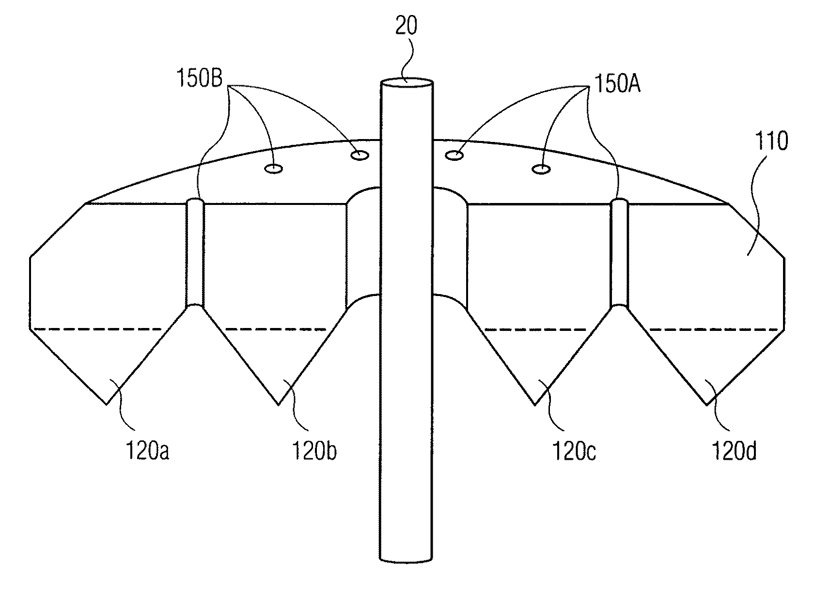
[0030]A solution embodying the invention, aimed at reducing the impact of water slamming while maintaining power production includes a float for a WEC, where the underside of the float, intended to be impacted by the waves, is wedge shaped (e.g., it is triangular in cross section with the apex of the triangle pointing away from the top surface of the float).

[0031]FIGS. 3, 4A and 4B show a float 110 embodying the invention which has a central opening so the float can move up and down relative to a central shaft or spar 20. FIGS. 4A and 4B are different isometric views of the top and underside of the float whose cross section, as shown in FIG. 3, may be represented as having two triangular / wedge sections, 120a, 120b. The float 110 extends radially and symmetrically about the shaft 20 which defines a central axis of symmetry of the WEC. The float 110 has: (a) an upper section having a toroidal configuration, of height H1, with the toroid extending along the horizontal (x) direction (th...


PUM

PropertyMeasurementUnit
acute angleaaaaaaaaaa
depthaaaaaaaaaa

Abstract

A float structure for a WEC is designed to have a tapered underside to reduce the impact due to wave slam and bending moments while providing little reduction in the surface area responding to the wave surface in order to maintain the beneficial power generating capability of a “flat” float. The underside of the float presents an inverted wedge section to decrease loads associated with wave slamming. The float may have a generally toroidal or elliptical configuration at and about the “still” water line with the generally submerged underside of the float having a cross section shaped to have one or more inverted triangular sections extending between the outer perimeter of the float and its center to reduce impact loading due to wave slamming while maintaining power producing capability.

Description

[0001]This invention claims priority from provisional application Ser. No. 61 / 199,881 filed Nov. 21, 2008 for FLOAT FOR WAVE ENERGY CONVERTER (WEC) whose teachings incorporated herein by reference.BACKGROUND OF THE INVENTION[0002]This invention relates to apparatus for converting energy present in surface waves of bodies of water into useful electrical energy and, in particular, to the design of floats (or shells) for use in wave energy converters (WECs) to improve the power generation efficiency and survivability of the WECs.[0003]Various wave energy converter (WEC) systems are known. For example, reference is made to U.S. Pat. No. 6,921,904 titled “Wave Energy Converter Utilizing Pressure Difference”; U.S. Pat. No. 6,617,705 titled “Protector Arrangement For Natural Energy Power Generation Systems” and U.S. Pat. No. 7,141,888 titled “Antirotational Structures For Wave Energy Converters” all assigned to the assignee of the present application, and the teachings of which are incorpo...

Claims


Application Information

Patent Timeline
Patent Type & Authority Patents(United States)
IPC IPC(8): F03B17/02F03B13/18
CPCE02B9/08F03B13/1845Y10T29/49826Y02E10/38Y02E10/30
Inventor GERBER, JAMES S.PHELAN, CHRISTOPHER THOMASQIU, WEISPENCER, DONALD SMITH
Owner OCEAN POWER TECHNOLOGIES
Why Eureka
Try Eureka