Light-guide concrete-based photovoltaic solar structure unit and pavement construction method

A photovoltaic solar energy and structural unit technology, applied in the field of photovoltaic solar energy, can solve the problems of high cost, uneconomical cost, and small friction coefficient of plexiglass materials, etc., and achieve the effects of strong mechanical properties, broad application prospects, and good power generation performance

Active Publication Date: 2016-05-11
CHANGSHA UNIVERSITY OF SCIENCE AND TECHNOLOGY
View PDF7 Cites 12 Cited by
  • Summary
  • Abstract
  • Description
  • Claims
  • Application Information

AI Technical Summary

Problems solved by technology

[0002] Photovoltaic solar pavement power generation technology was introduced in the patent application 201410142523.X. This technical solution solves the problem of power generation and storage, but the top layer of the structure uses plexiglass to achieve the purpose of protection and light transmission, and there are the following shortcomings: First, The unit price of plexiglass is high, which leads to uneconomical cost of the structure as a whole; second, the friction coefficient of plexiglass material is small, and the anti-slip performance of the structure surface mainly depends on the depth of the structure, the anti-slip effect is not ideal, and it also has an adverse effect on the lighting performance
[0004] In order to achieve the purpose of using solar power on the road surface, light-guiding concrete can be used, but there are still several problems: (1) The problem of structural design, the existing light-guiding concrete is mostly used for wall lighting and art design; (2) The selection and arrangement of light-guiding materials. In order to improve the light transmittance of existing light-guiding concrete, the distance between optical fibers or resins used is mostly millimeter-level, which requires extremely high construction technology and high cost; (3) ) Cement mortar cannot meet the requirements of road surface strength and road performance

Method used


Image

  • Light-guide concrete-based photovoltaic solar structure unit and pavement construction method
  • Light-guide concrete-based photovoltaic solar structure unit and pavement construction method
  • Light-guide concrete-based photovoltaic solar structure unit and pavement construction method

Examples


Embodiment Construction

[0038] The present invention will be described in further detail below in conjunction with the accompanying drawings and specific embodiments.

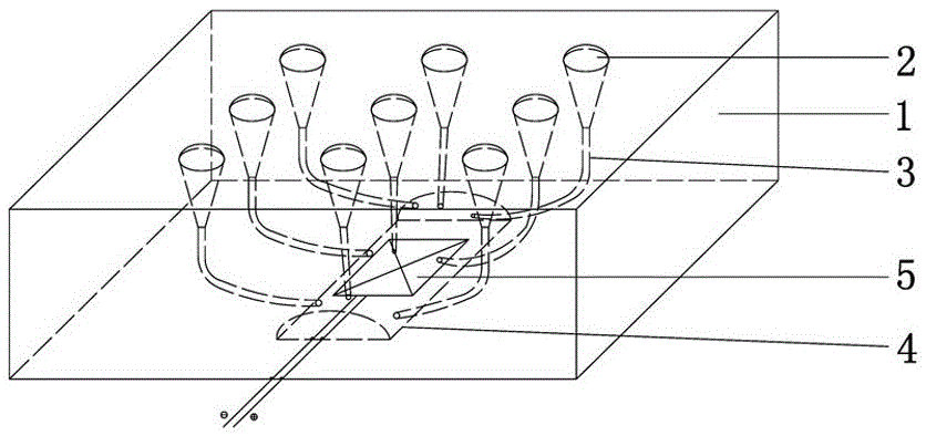
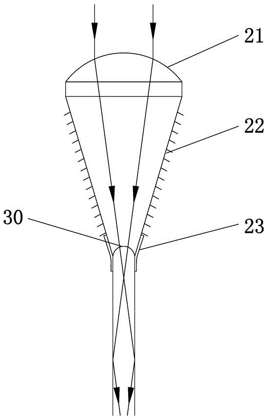
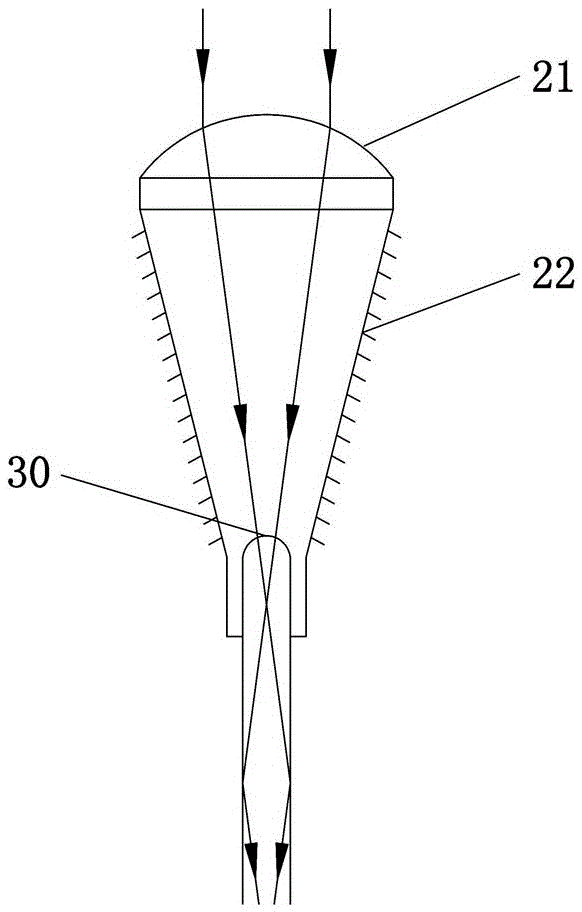
[0039] Figure 1 to Figure 4 It shows an embodiment of a photovoltaic solar structural unit based on light-guiding concrete of the present invention, which includes a concrete base 1, a light-collecting part 2, an optical fiber 3, a protective cover 4 and a photovoltaic solar panel 5, and the protective cover 4 is located on the concrete A closed cavity for placing photovoltaic solar panels 5 is formed between the bottom of the base 1 and the concrete base 1. The concentrating part 2 is located on the top of the concrete base 1. One end of the optical fiber 3 is connected to the concentrating part 2, and the other end passes through the protective cover 4 and point to the photovoltaic solar panel 5 . In the photovoltaic solar structural unit based on light-guiding concrete of the present invention, its concentrating part 2, optical f...


PUM


Abstract

The invention discloses a light-guide concrete-based photovoltaic solar structure unit and a pavement construction method. The photovoltaic solar structure unit comprises a concrete substrate, a light converging part, an optical fiber, a protective cover and a photovoltaic solar panel, wherein the protective cover is located at the bottom part of the concrete substrate; a closed hollow cavity for placing the photovoltaic solar panel is formed between the protective cover and the concrete substrate; the light converging part is located at the top part of the concrete substrate; one end of the optical fiber is connected with the light converging part; and the other end passes through the protective cover and points at the photovoltaic solar panel. The pavement construction method comprises the following steps: (S1) prefabricating a plurality of photovoltaic solar structure units; and (S2) splicing the photovoltaic solar structure units into an overall pavement structure in order. The light-guide concrete-based photovoltaic solar structure unit has the advantages of good generating performance, high mechanical property, high construction efficiency, wide application prospect and the like.

Description

technical field [0001] The invention relates to photovoltaic solar technology, in particular to a photovoltaic solar structural unit and a road surface construction method based on light-conducting concrete. Background technique [0002] Photovoltaic solar pavement power generation technology was introduced in the patent application 201410142523.X. This technical solution solves the problem of power generation and storage, but the top layer of the structure uses plexiglass to achieve the purpose of protection and light transmission, and there are the following shortcomings: First, The unit price of plexiglass is high, which leads to uneconomical cost of the structure as a whole; second, the friction coefficient of plexiglass material is small, and the anti-slip performance of the structure surface mainly depends on the depth of the structure, the anti-slip effect is not ideal, and it also has an adverse effect on the lighting performance . Therefore, choosing a suitable lig...

Claims


Application Information

Patent Timeline
Patent Type & Authority Applications(China)
IPC IPC(8): H02S20/10H02S40/22E01C5/06
CPCY02E10/52H02S20/00E01C5/06H02S40/00
Inventor 查旭东张铖坚肖景文刘昕宇付昊彭幸海李东晟
Owner CHANGSHA UNIVERSITY OF SCIENCE AND TECHNOLOGY
Why Eureka
Try Eureka