Dental implant

a technology of dental implants and implants, applied in dental implants, dental surgery, medical science, etc., can solve the problems of short or significant thin length of available alveolar bone, failure of osseointegration, and inability to fully integrate, and achieve the effect of prolonging the li

Active Publication Date: 2013-09-03
NEOBIOTECH
View PDF11 Cites 4 Cited by
  • Summary
  • Abstract
  • Description
  • Claims
  • Application Information

AI Technical Summary

Benefits of technology

[0017]The present invention provides a short implant that may be successfully implanted without a vertical alveolar bone graft even when osseous tissues are weak or when vertically very short bone mass remains.
[0018]The present invention also provides a dental implant that may provide a sufficient bearing power while an outer diameter of an implant body is relatively small compared to a conventional implant and a section size thereof decreases.
[0019]The present invention also provides a dental implant that may be implanted without the need for a vertical bone graft even in a narrow and thin bone structure, and also provides a dental implant that may not be unnecessarily exposed in correspondence to the shape of an alveolar bone having a narrow upper portion and may be rapidly recovered from damage to the alveolar bone.

Problems solved by technology

When the external force is applied in a state where the sufficient osseointegration is not achieved, the implant surface and the bone structure may not directly contact with each other and, instead, soft tissue may be interposed therebetween, which may result in the failure of osseointegration, that is, the failure of implant.
On the other hand, the length of available alveolar bone may be short or significantly thin.
When a tooth is unattended after its extraction for a long period of time, or when a tooth is extracted due to serious gum disease, the alveolar bone may be significantly damaged and only short and thin alveolar bone may remain.
The vertical bone graft is difficult and has a very low success rate.
A conventional short implant has an insufficient capability for enduring an occlusion force and thus, more implants may need to be implanted and need a longer waiting period than the long implant and thus, may easily fail due to a weak force against the occlusion force.
In a case where an upper portion of alveolar bone is thin, when a conventional implant with a small diameter is implanted to prevent the exposure of the implant, the implant may not endure the occlusion force, thereby causing implant fracture.
However, the horizontal bone graft operation may cause greater pain and require long operation time in a patient side and may be hard on a dentist side.
In this case, when a prosthesis is installed, a force against an external force may decrease and a greater force may be concentrated on the alveolar bone whereby a bone loss may further quickly occur.
Accordingly, it becomes an important issue to maintain the bone of the proximal portion for a long period of time.
When the thickness of bone tissue becomes to be smaller than 1.5 mm-2 mm, the bone loss may easily occur.
In this case, when the implant of which the diameter of the proximal portion is large is implanted, the bone loss may occur.
Therefore, in many cases, a difficult bone graft may need to be accompanied to reinforce the thickness of alveolar bone.
Since the masticatory pressure may be applied immediately after implantation, the weakly implanted implant may easily fail.
However, even the submerged or non-submerged implant still needs the secondary operation in many cases and needs to form a connecting groove within the proximal portion of the implant in order to later connect the abutment to the implant.
Therefore, due to the empty inside, the strength may be weakened and the proximal portion may need to be maintained to have a possibly large diameter.
In the case of the submerged or non-submerged implant, it is difficult to decrease the diameter of the proximal portion and the inside structure is weak, thereby causing continuous implant fracture by an occlusion force.
Also, due to a micro-gap of the connecting portion, the bone loss may increase.
A circumstance where a patient has to make a living for a long period of time without a tooth may bring a mental and physical pain to the patient.
In many cases, the patient may not make a normal social life.

Method used


Image

  • Dental implant
  • Dental implant
  • Dental implant

Examples


Embodiment Construction

[0051]Reference will now be made in detail to embodiments of the present invention, examples of which are illustrated in the accompanying drawings, wherein like reference numerals refer to the like elements throughout. The embodiments are described below in order to explain the present invention by referring to the figures.

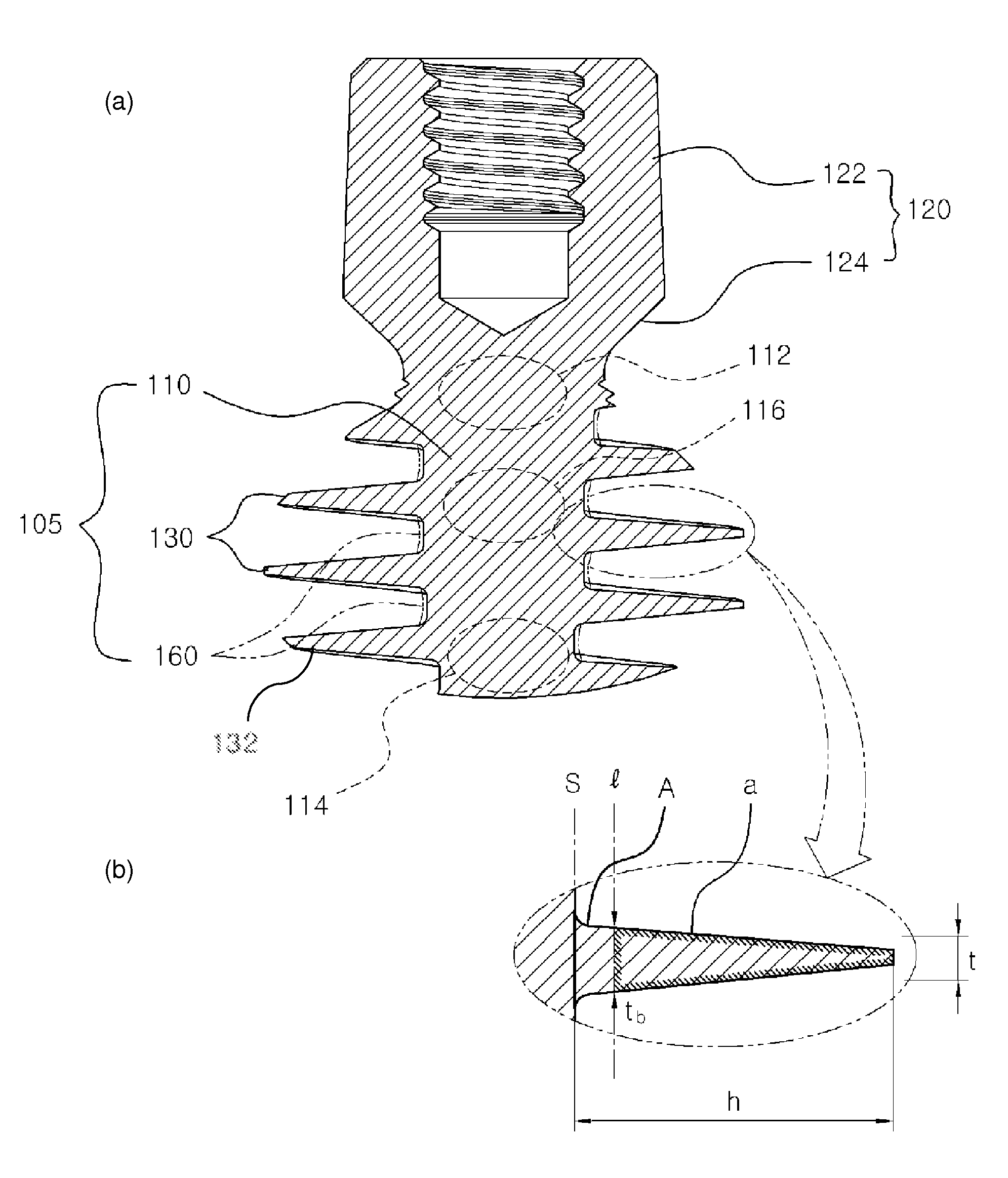
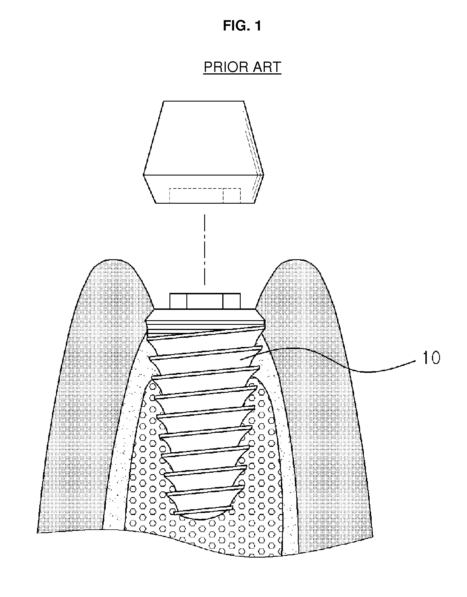
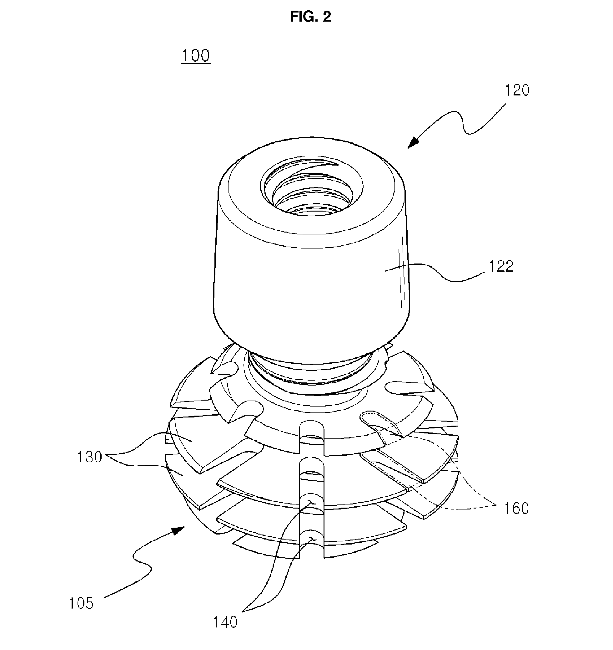
[0052]FIG. 2 is a perspective view illustrating an implant 100 according to an embodiment of the present invention, FIG. 3 is a sectional view illustrating the implant 100 of FIG. 2, and FIG. 4, parts (a) and (b), illustrate sectional views to compare a usage example of the implant 100 of FIG. 2 and the conventional art.

[0053]Referring to FIG. 2 through FIG. 4, the implant 100 for a dental operation according to an embodiment of the present invention comprises a body portion 105 and a mounting portion 120. The body portion 105 and the mounting portion 120 are integrally formed with each other and may be formed using a bioaffinity material such as titanium, zirconi...


PUM


Abstract

A dental implant of the invention allows an immediate masticatory function just after being implanted in a bone structure, does not need a secondary operation, and can be effectively applied even in thin and short alveolar bone. The dental implant comprises a body portion to be inserted in the bone structure and a mounting portion integrally formed on the body portion, the body portion including a thin and short core, screw blades formed along an outer peripheral surface of the core in the shape of a wide and deep screw, and a connecting portion formed in the shape of a plurality of vertical holes and grooves and capable of containing bone growth factors. The mounting portion has a gum adhering portion to protect bone tissues and a post to be mounted with an abutment or a prosthesis thereon.

Description

REFERENCE TO RELATED APPLICATIONS[0001]This application claims priority to PCT / KR2010 / 000686 filed on Feb. 4, 2010, which designates the United States and claims priority of Korean Patent Application No. 10-2009-0015155 filed on Feb. 24, 2009, the entire contents of which are incorporated herein by reference.FIELD OF THE INVENTION[0002]The present invention relates to a dental implant implanted in an upper portion of alveolar bone within the oral cavity. More particularly, the present invention relates to a dental implant that may relatively quickly perform its functionality within a relatively short period of time compared to a conventional implant, may decrease damage to the alveolar bone, and may effectively cope with formation of the alveolar bone.BACKGROUND OF THE INVENTION[0003]An implant corresponds to a structure that is to be implanted in a bone of a living body for the purpose of treatment. The implant may be used when mounting a prosthesis on the alveolar bone instead of ...

Claims


Application Information

Patent Timeline
Patent Type & Authority Patents(United States)
IPC IPC(8): A61C8/00
CPCA61C8/0022A61C8/0018A61C8/00
Inventor HEO, YOUNG KU
Owner NEOBIOTECH
Why Eureka
Try Eureka