Wind tunnel convergent type power generator

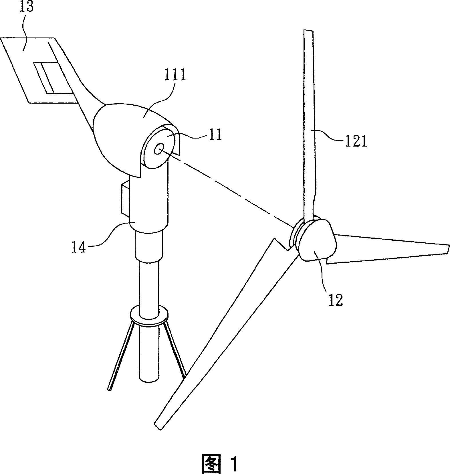
A technology of generators and wind tunnels, which is applied to wind turbine components, wind engines, wind engine control, etc., and can solve problems such as the inability of the empennage 13 to control the steering of the wind turbine 1, the inability to use the wind and the empennage, and increase the area.

Inactive Publication Date: 2007-08-01
IND TECH RES INST
View PDF0 Cites 12 Cited by
  • Summary
  • Abstract
  • Description
  • Claims
  • Application Information

AI Technical Summary

Problems solved by technology

[0004] However, in order to increase the generating power, the wind generator 1 generally achieves the effect of generating relatively large energy at a relatively small wind speed by increasing the area of ​​the blades 121, and generally increases the length of the blades 121 to achieve the purpose of increasing the area, so that the wind force The generator 1 must be suitable for use in a larger space, and the longer blades 121 also make the wind generator have a heavier weight
Moreover, in order to avoid damage to the wind power generator 1 due to excessive wind speed, a wind speed at shutdown can be set, so that the wind with a higher wind speed cannot be used to generate electricity
In addition, because the empennage 13 passively controls the direction of the wind turbine 1 through the wind direction, it is sometimes impossible to face the windward side accurately, and even the wind direction is 0 degrees, 90 degrees to the windmill 12 of the wind turbine 1. degrees or 270 degrees, it may cause the empennage 13 to be unable to play the effect of controlling the steering of the wind turbine 1
[0005] In view of the fact that the known wind generators need to occupy a large space, cannot utilize the wind of higher wind speed and the empennage may not be able to exert the effect of controlling the steering of the wind generator, so the present invention which can effectively improve the above-mentioned problems is proposed

Method used


Image

  • Wind tunnel convergent type power generator
  • Wind tunnel convergent type power generator

Examples


Embodiment Construction

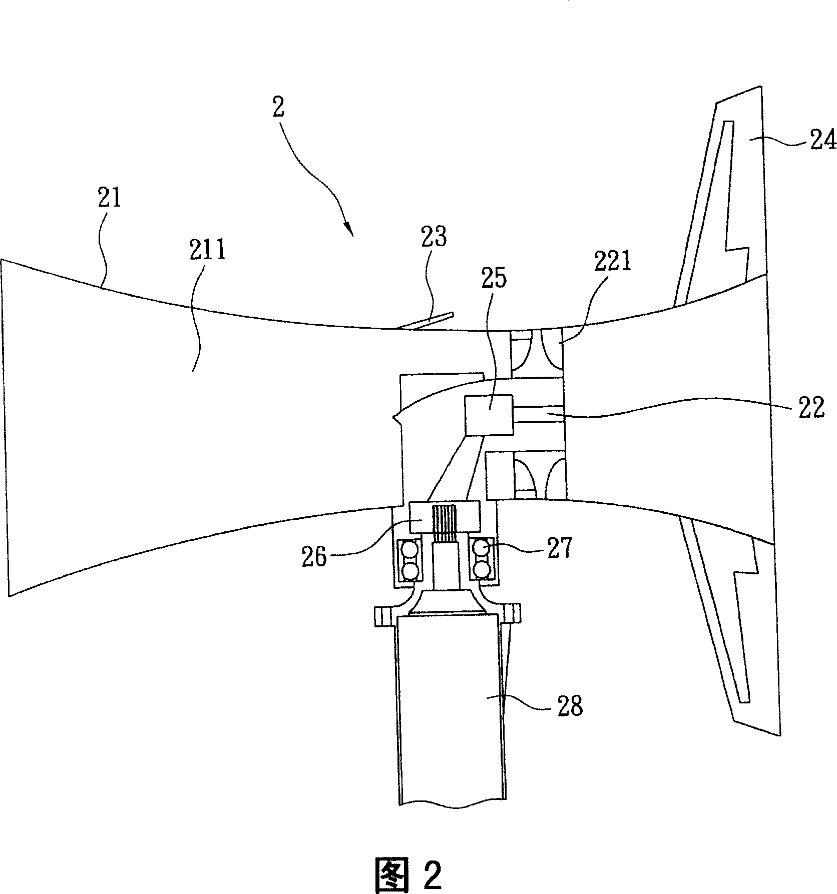
[0021] Referring to Fig. 2, the present invention provides a wind tunnel convergence type power generator 2, which includes an outer cover 21, a turbine rotor 22, a discharge valve 23 and an empennage 24; the outer cover 21 is a circular tube and presents a tapered and then gradually expanded appearance , and a single or combined outer cover made by metal or composite material molding such as casting, and the turbine rotor 22 is arranged in the inner flow channel 211 formed by the outer cover 21, and is located between the taper and the outer cover 21. In the gradually expanding throat portion, the axis line of the turbine rotor 22 coincides with the axis line of the casing 21 . In addition, the air release valve 23 is arranged adjacent to the turbine rotor 22 and is located on the wall of the housing 21 in the air inlet direction; as for the empennage 24, it is arranged on the surface of the housing 21 positioned at the air outlet end in a direction perpendicular to the axis l...


PUM


Abstract

A wind tunnel collecting generator comprises a frame, a turbine rotor, a snuffle valve and a tail wing. The frame is reduced stepped and then expanded. The turbine rotor is arranged in the frame. The snuffle valve is on the wall of the frame. The tail wing is arranged on the face of frame. Via the acceleration of frame, the improved efficiency of turbine rotor and the reduced pressure of snuffle valve, the inventive generator can own wide operation range, low occupied space, low heavy, low noise and high efficiency.

Description

technical field [0001] The invention relates to a wind tunnel convergence type power generator, in particular to a wind tunnel convergence type power generator with small volume and high efficiency. Background technique [0002] As the world's oil production decreases and the greenhouse effect becomes more and more serious, countries around the world are committed to developing non-polluting energy, so wind power and solar power have become popular targets. [0003] Known wind power generator 1 (as Fig. 1), it comprises generator body 11, windmill 12, empennage 13 and fixed frame 14; Fixed frame 14 connects generator body 11 with a bearing (figure omitted), and generator body 11 The windmill 12 is connected with another bearing, and a plurality of blades 121 are arranged on the windmill 12, and the blades 121 and the axis line of the rotating shaft connected to the windmill 12 all have a fixed acute angle, and the empennage 13 is arranged on the shell of the generator body 1...

Claims


Application Information

Patent Timeline
Patent Type & Authority Applications(China)
IPC IPC(8): F03D1/00F03D1/04F03D1/06F03D11/00F03D7/02F03D11/04F03D13/20
CPCY02E10/723Y02E10/728Y02E10/721Y02E10/72
Inventor 熊道邦詹嘉维魏增武
Owner IND TECH RES INST
Why Eureka
Try Eureka