Polymer Electrolyte Fuel Cell Stack

一种高分子电解质、燃料电池组的技术,应用在固体电解质燃料电池、燃料电池分组、燃料电池等方向,能够解决联接载荷过大、联接载荷过大或过小、电池组体积增大等问题,达到联接容易、装配性优异、发电性能及耐久性改善的效果

Active Publication Date: 2011-12-14
PANASONIC CORP
View PDF12 Cites 12 Cited by
  • Summary
  • Abstract
  • Description
  • Claims
  • Application Information

AI Technical Summary

Problems solved by technology

In the methods described in Patent Documents 1, 3, and 4, since the connection is performed only by the residual stress preloaded on the strips, the problem that the connection load is too large or too small occurs when the thickness of the laminated body varies.
Also in Patent Document 6, since the plates are joined only by the preloaded residual stress when joining each other, when the thickness of the laminated body varies, the joining load may be too large or too small.
[0022] In addition, in the methods shown in Patent Documents 2, 5, and 7, the load can be adjusted by bolts or disk springs for the thickness variation of the laminated body, but the volume of the battery pack may increase due to the bolts used for adjustment. The problem

Method used


Image

  • Polymer Electrolyte Fuel Cell Stack
  • Polymer Electrolyte Fuel Cell Stack
  • Polymer Electrolyte Fuel Cell Stack

Examples


no. 1 example

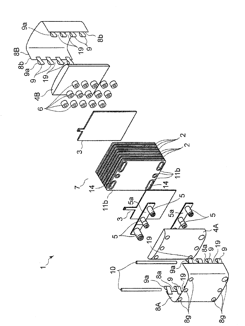
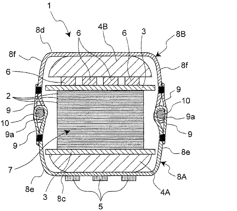
[0075] Figure 3A and Figure 3B A cross-sectional plan view of the fuel cell stack 1 in the first example of the present embodiment and its modifications is shown in . Collector plates 3 are arranged on the upper and lower sides of the battery cell stack 7, and pipes 5 are placed near one collector plate 3 on the lower side of the battery cell stack 7, pressed against by the end plate 4A, and the other collector plate on the upper side is pressed. A plurality of inner springs 6 are arranged on the plate 3, and are clamped by the upper and lower end plates 4A, 4B. The whole member to be connected is covered with two straps 8A, 8B having strap main parts 8c, 8d having the same width as the battery unit 2. As an example, the straps 8A, 8B are connected by two pins 10 to connect them. When the assembly is completed with the strips 8A, 8B and the pins 10, the plurality of inner springs 6 on the collector plate 3 are compressed between the battery cell stack 7 and the end plate 4...

no. 2 example

[0105] The cross-sectional shape of the pin 10 is not limited to the circular shape of the first embodiment, but may be of any shape, and examples of shapes other than the circular shape will be described below. For example, Figure 8 (1) is for comparison with Figure 6 (1) is the same, and is a cross-sectional plan view of a state in which the connecting portion 9 is connected using the pin 10A having a circular cross-sectional shape in the first embodiment.

[0106] in comparison, Figure 8 (2) shows an enlarged sectional plan view of the joint portion 9 and the pin 10E of the strap 8 in the second embodiment. As the pin 10E to be used, a rod having an oblong cross-sectional shape perpendicular to its longitudinal direction is used. In this second embodiment, a pin 10E having an oblong cross-sectional shape whose length in the major axis direction is a multiple (double) of the length in the minor axis direction is used as the coupling load, which is similar to that of th...

no. 3 example

[0109] Figure 8 (4) shows an enlarged cross-sectional plan view of the vicinity of the coupling portion 9 of the strap 8 in the third example of the above-described embodiment. For the coupling of the link 9 of the strap 8, several pins 10G of the same kind are used, whereby the coupling load can be adjusted. In the third embodiment, when the thickness of the battery cell stack 7 is thin, both pins 10G are inserted into the connection portion 9 and one connection portion of the connection portion 9, that is, both pins are inserted into the connection portion 9. In one through hole 9a, the connection load can be adjusted according to the thickness deviation of the battery cell stack 7 corresponding to the diameter and length of the pin 10G. There is no need to increase the volume of the battery pack 3, and there is no need to prepare different types of pins 10 having different diameters and cross-sectional shapes, and the assembly of the battery pack can be completed, which i...


PUM


Abstract

When assembly is carried out by clamping a stacked product (7) made up of a plurality of unit cell modules (2), paired end plates (4A, 4B) respectively disposed on both the sides thereof and the like by a plurality of fastening members (8A, 8B, 8F), first coupling portions (9) of one end portion of each of such plurality of fastening members and second coupling portions (9) of the other end portions are combined to each other, and coupled with one pin member (10, 10A, 10B, 10E, 10G). Thus, a plurality of such fastening members are coupled.

Description

technical field [0001] The present invention relates to a solid polymer electrolyte fuel cell stack of a normal temperature operation type used in a portable power supply, a power supply for an electric vehicle, or a home heating and power simultaneous supply system. Background technique [0002] A fuel cell using a polymer electrolyte generates electricity and heat simultaneously by electrochemically reacting a hydrogen-containing fuel gas with an oxygen-containing oxidant gas such as air. This fuel cell is basically composed of a polymer electrolyte membrane that selectively transports hydrogen ions, and a pair of electrodes, that is, an anode and a cathode formed on both sides of the polymer electrolyte membrane. These electrodes have a catalyst layer mainly composed of carbon powder carrying a platinum group metal catalyst and formed on the surface of a polymer electrolyte membrane, and a gas-diffuser layer that is arranged outside the catalyst layer and has both gas per...

Claims


Application Information

Patent Timeline
Patent Type & Authority Applications(China)
IPC IPC(8): H01M8/24H01M8/04H01M8/10
CPCH01M8/248Y02E60/50H01M2008/1095H01M8/247H01M8/2475
Inventor 山本曜子
Owner PANASONIC CORP
Why Eureka
Try Eureka