Lightning protection structure of blade for wind power generation

a technology of blade protection and wind power generation, which is applied in the installation of lighting conductors, machines/engines, mechanical equipment, etc., can solve the problems of increasing the damage of the lightning receptor around the lightning receptor and the lightning itself, and the damage of the lightning receptor may not be restrained, so as to improve the function of arresting lightning, improve the effect of aerodynamic characteristics and reliably attach the lightning receptor to the blad

Active Publication Date: 2015-10-27
JAPAN STEEL WORKS LTD
View PDF31 Cites 11 Cited by
  • Summary
  • Abstract
  • Description
  • Claims
  • Application Information

AI Technical Summary

Benefits of technology

[0013]With the interposition of the ceramic member, when the lightning receptor arrests the lightning, the electric field first concentrates at the tip end of the lightning receptor or the interface between the lightning receptor and the ceramic member. As a result, it is possible to prevent the blade from being damaged due to that the electric field concentrates at the interface of the blade. Since the ceramic member is excellent in heat resistance and electric insulation, it is hard to be damaged by the concentration of the electric field. Since the ceramic member is positioned over the entire circumference between the lightning receptor and the blade, it is possible to certainly prevent the electric field from concentrating at the interface of the blade.
[0015]When placing the ceramic member, it is preferable that a surface of the blade and a surface of the ceramic member are formed to be flush with each other. As a result, it is possible to avoid the concentration of the electric field at the interface between the blade and the ceramic member due to the lightning, and to obtain the excellent performance in view of aerodynamics. Further, a good aerodynamic characteristic is obtained by forming the surface of the ceramic member and the surface of the lightning receptor to be flush with each other, so that power generation performance is maintained very well.
[0019]The lightning receptor is attached to the tip end of the blade. At the tip end of the blade, the lightning receptor may have a tapered shape (tapered in a direction seeing the surface of the blade) continuing from the shape of the blade and its width is gradually reduced toward its tip end. According thereto, it is possible to improve the function of arresting the lightning while ensuring favorable aerodynamic characteristics.
[0020]In addition, in order to reliably attach the lightning receptor to the blade, the lightning receptor may be provided with an anchor part, and the anchor part may be fixed to the blade. The anchor part penetrates through a hollow portion of the ceramic member so as to reach and be positioned in the blade, so that the anchor receptor may be certainly fixed to the blade without having a bad effect on the function of the ceramic member. Specifically, by forming an insertion / penetration hole in the ceramic member and by inserting and penetrating the anchor part through the insertion / penetration hole, the ceramic member may be held by the blade and the anchor part fixed to the blade. In order to improve the holding effect, the insertion / penetration hole may be adapted to the shape of the anchor part, so that a lateral wall of the anchor part is in close contact with the insertion / penetration hole when the anchor part is inserted and penetrated through the insertion / penetration hole.

Problems solved by technology

However, as the wind power generator grows in size, damage of the blade struck by the lightning is increased.
However, with the shapes of the lightning receptors proposed by Patent Literatures 2 and 3, a damage around the lightning receptor and of the lightning receptor itself due to lightning strike may not be restrained.

Method used


Image

  • Lightning protection structure of blade for wind power generation
  • Lightning protection structure of blade for wind power generation
  • Lightning protection structure of blade for wind power generation

Examples


embodiment 1

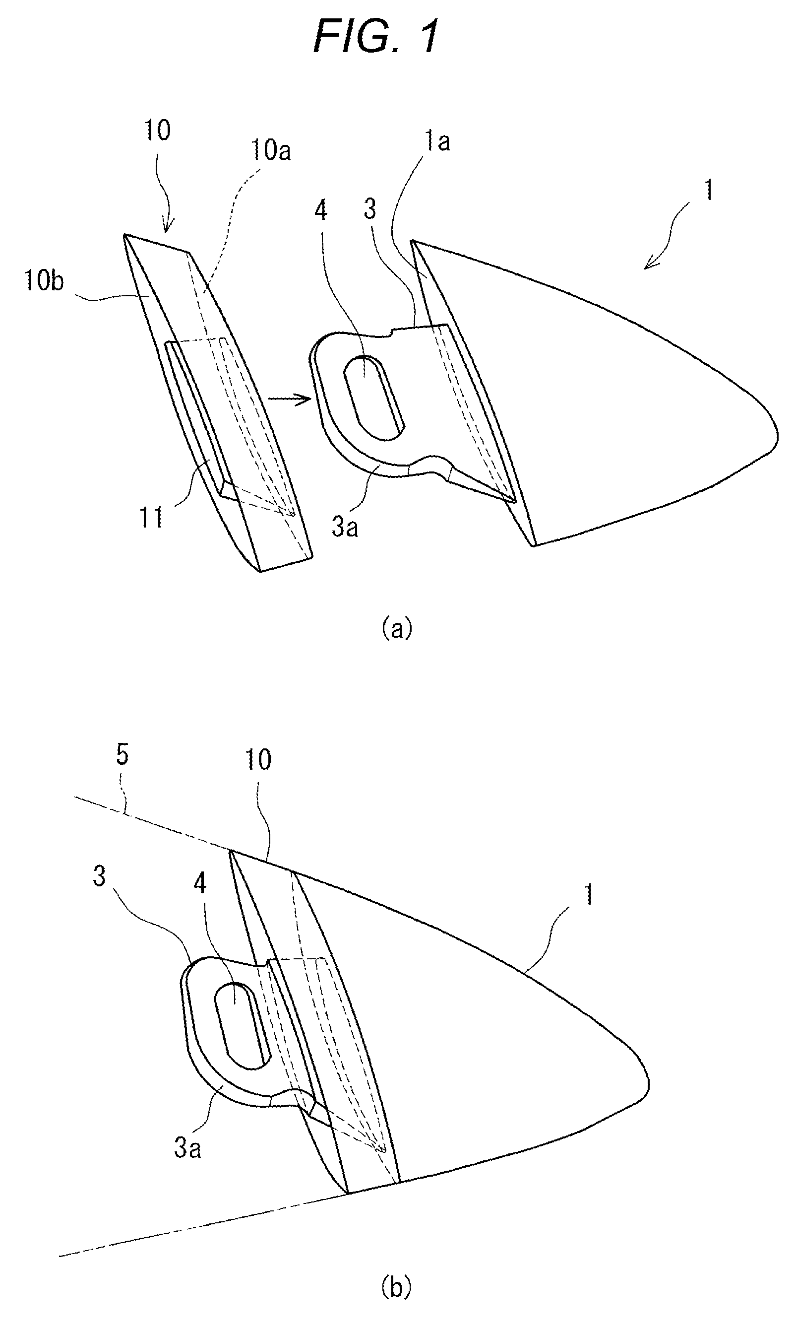
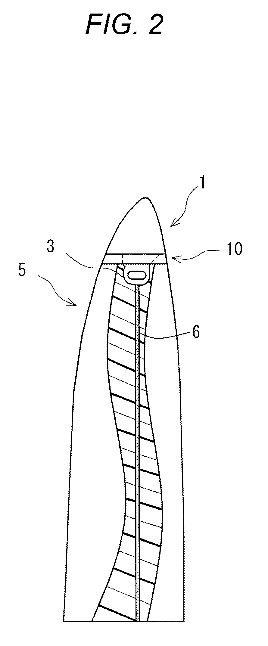
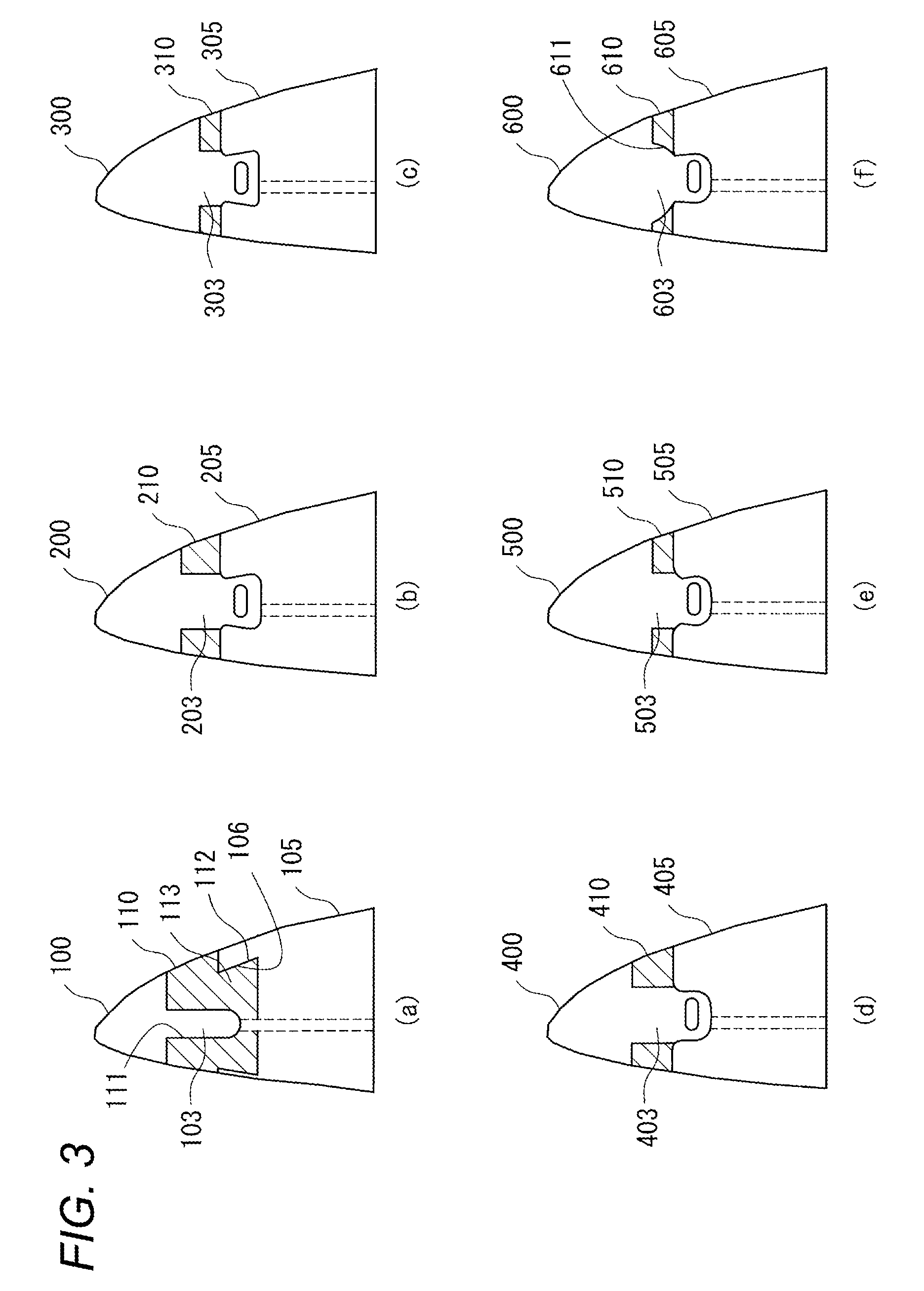
[0054]Next, the lightning protection structure including the lightning receptor 1 made of aluminum and the ceramic member 10 according to the embodiment of the present invention illustrated in FIG. 1 and a lightning protection structure including a lightning receptor 20, with no ceramic member is interposed, according to the related art illustrated in FIG. 6 were attached to an FRP material imitated as a blade. Then, those lightning protection structures were subjected to 2-D electric field analysis using simulation to predict a position struck by the lightning.

[0055]Incidentally, in the analysis, an analysis software MARC2007R1 (a product manufactured by MSC Software Corporation) was utilized, and a point charge was placed at a distance of 1 m from the tip end portion of the blade. Letting a position immediately above the tip end portion of the blade to be 0°, point charges were placed at positions of ±30°, ±60°, and ±90°, and positions of 200 mm and 500 mm lowered immediately belo...


PUM


Abstract

To effectively perform lightning protection in a blade for wind power generation and to prevent the blade from being damaged when arresting lightning. The lightning protection structure of the blade for wind power generation includes a conductive lightning receptor 1 attached to a part of the blade for wind power generation, and a ceramic member 10 interposed between at least surface-layer portions of the lightning receptor 1 and the blade 5. Therefore, an electric field is likely to concentrate at an interface between the ceramic member 10 having excellent heat resistance and the lightning receptor 1, so that it is possible to effectively prevent the blade 5 from being damaged due to a concentration of the electric field at the interface of the blade 5 attached with the lightning receptor 1 when arresting the lightning.

Description

TECHNICAL FIELD[0001]The present invention relates to a lightning protection of a blade for wind power generation to prevent damage of the blade which is utilized for the wind power generation.BACKGROUND ART[0002]Blades for wind power generation currently used is mainly made of glass fiber reinforced plastics (GFRP), and the blade itself is an insulator and has no electrical conductivity. Accordingly, in an era when a small wind power generator was used, it was considered that the blade was not struck by lightning. However, as the wind power generator grows in size, damage of the blade struck by the lightning is increased. Accordingly, a method of attaching a member (e.g., lightning receptor) made of metal to the blade and connecting a lead line (e.g., down conductor) to the metallic member so as to lead the lightning to the ground has been generalized (for example, refer to Background-Art section of Patent Literature 1).[0003]Various shapes or types of the lightning receptors have ...

Claims


Application Information

Patent Timeline
Patent Type & Authority Patents(United States)
IPC IPC(8): F03D11/00F03D1/06H02G13/00
CPCF03D1/0675F03D11/0033H02G13/00H02G13/80F05B2280/2004F05B2280/5002Y02E10/721Y02E10/722F03D80/30Y02E10/72F05B2240/307F05B2240/30
Inventor MUTO, ATSUTOSHI
Owner JAPAN STEEL WORKS LTD
Why Eureka
Try Eureka