Safety device, system and method of use

Active Publication Date: 2017-12-07
MAKUSAFE CORP
View PDF9 Cites 8 Cited by
  • Summary
  • Abstract
  • Description
  • Claims
  • Application Information

AI Technical Summary

Benefits of technology

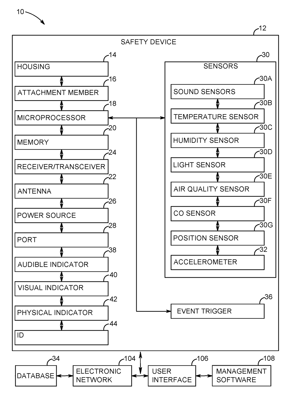
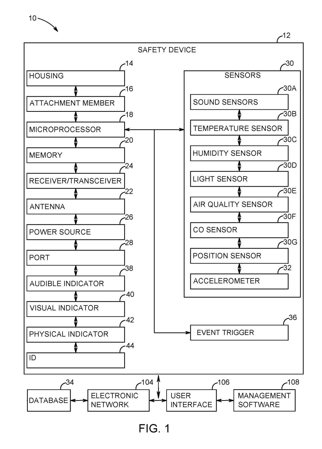
[0045]A safety device that is worn by a worker in a manufacturing facility is presented. The safety device includes a microprocessor, memory, an antenna and transceiver and a plurality of sensors that sense environmental conditions surrounding the worker such as light levels, noise levels, temperature, humidity, air quality and CO levels. The safety device also tracks the position of the worker and includes an accelerometer that detects trips and falls. Th

Problems solved by technology

Injuries at work are tremendously costly for both the corporation as well as the injured worker.
In view of the personal cost to the injured worker and the financial cost to the employer, a great amount of energy and effort has been placed on avoiding workplace injuries.
However, despite these many efforts, avoidable injuries continue to occur at an alarming pace.
Due to the complex nature of today's modern manufacturing facility, the root causes of these workplace injuries are often difficult to discern.
This complexity makes it even more difficult to predict when, where, why and how an injury may occur in the future.
However, collecting this information, especially in aggregate,

Method used


Image

  • Safety device, system and method of use
  • Safety device, system and method of use
  • Safety device, system and method of use

Examples


Embodiment Construction

[0067]In the following detailed description, reference is made to the accompanying drawings which form a part hereof, and in which is shown by way of illustration specific embodiments in which the disclosure may be practiced. These embodiments are described in sufficient detail to enable those skilled in the art to practice the disclosure, and it is to be understood that other embodiments may be utilized and that mechanical, procedural, and other changes may be made without departing from the spirit and scope of the disclosure(s). The following detailed description is, therefore, not to be taken in a limiting sense, and the scope of the disclosure(s) is defined only by the appended claims, along with the full scope of equivalents to which such claims are entitled.

[0068]As used herein, the terminology such as vertical, horizontal, top, bottom, front, back, end, sides and the like are referenced according to the views, pieces and figures presented. It should be understood, however, th...


PUM


Abstract

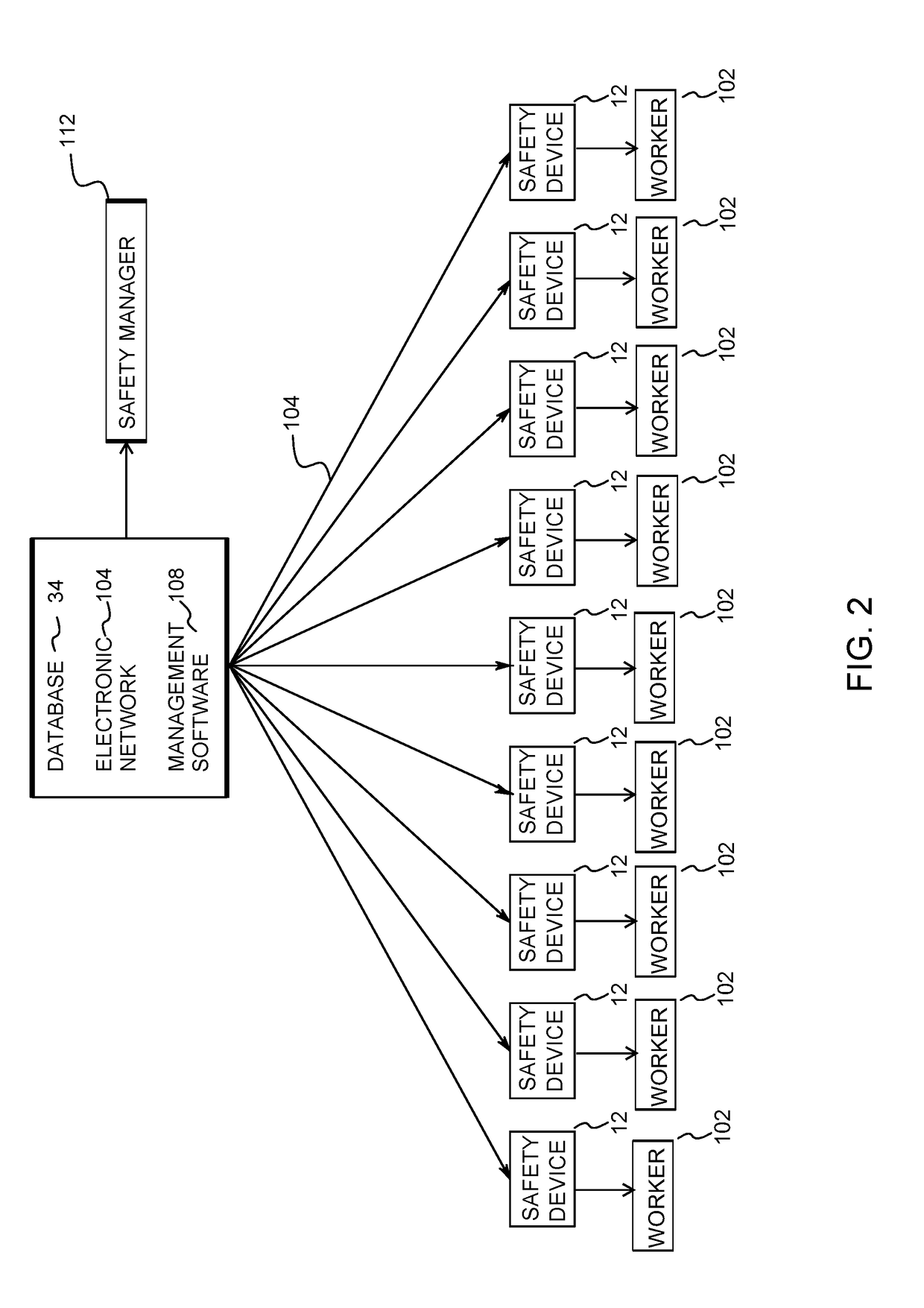
A safety device that is worn by a worker in a manufacturing facility is presented. The safety device includes a microprocessor, memory, an antenna and transceiver and a plurality of sensors that sense environmental conditions surrounding the worker such as light levels, noise levels, temperature, humidity, air quality and CO levels. The safety device also tracks the position of the worker and includes an accelerometer that detects trips and falls. The safety device also includes an event trigger which can be activated by the worker when a notable event or near miss occurs. The environmental information recorded by the safety device is used to both track accidents and near misses and is aggregated in a database for datamining purposes so as to predict future accidents and near misses. This information is also used to create correlations and better understand the root cause of accidents and near misses.

Description

CROSS-REFERENCE TO RELATED APPLICATIONS[0001]The present application claims priority to U.S. Provisional Patent Application No. 62 / 346,231 which was filed on Jun. 6, 2016, entitled SAFETY DEVICE, SYSTEM AND METHOD OF USE which is hereby incorporated by reference herein in its entirety, including any figures, tables, or drawings or other information.FIELD OF THE DISCLOSURE[0002]This disclosure relates to a safety device. More specifically and without limitation, this disclosure relates to a wearable safety device, system and method of use that is used to track and help predict workplace accidents and the environmental conditions surrounding workplace accidents.BACKGROUND OF THE DISCLOSURE[0003]Injuries at work are tremendously costly for both the corporation as well as the injured worker. As an example, it is estimated that 2016 will again see nearly 100 billion dollars in workers compensation claims. It is estimated that the average claim in the United State in 2016 will amount to o...

Claims


Application Information

Patent Timeline
IPC IPC(8): G08B21/14
CPCG08B21/14G08B21/0446G08B25/016G08B21/0469
Inventor GLYNN, GABRIELFREDERICK, MARKKRIER, DAVE
Owner MAKUSAFE CORP
Why Eureka
Try Eureka